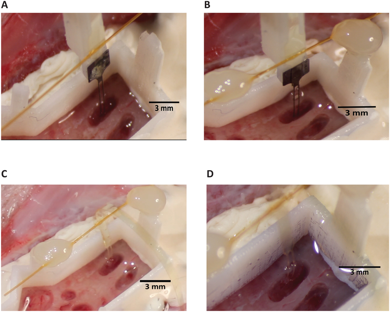
Figure 7: Retraction of shuttle.
(A) Tethering of wings before retraction. Two-shank array and shuttle shown. (B) PEG dissolution and wing adhesion with shank feature (circled, blue) that allows for visual confirmation of successful decoupling of array and shuttle during retraction. (C) A successful array insertion after insertion shuttle has been retracted. (D) Base piece with silicone gel fills for a single two-shank array insertion. The low-viscosity silicone gel used has a blue tint.

