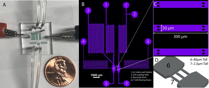
FIG. 1.
(a) Electrotaxis device showing fluid inlets, outlets, and electrotaxis electrodes. Channels filled with a colorimetric dye for imaging and penny shown for scale. (b) Confocal image of microfluidic channels filled with fluorescent dye Alexa Fluor 647 and labeled: 1. Standard buffer inlets, 2. Optional inlet for buffer switching, as might be useful for chemotaxis experiments, 3. Cell loading inlet, 4. Electrode ports, 5. Outlets, 6. 80 μm tall channel for cell seeding, 7. 2.3 μm tall constrictive channels for cell viewing during experimentation. (c) Zoomed in view of the three constrictive channels located in section 7. (d) 3D illustration of cell channels to depict height difference between section 7 and the main flow and cell loading channels. A micrograph of this region is shown in Fig. 2(b).

