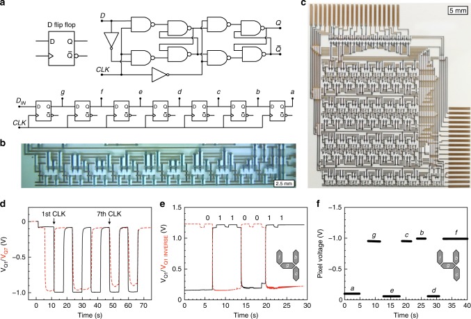
Fig. 5.
Seven-bit shift register based on organic electrochemical transistors. a Schematic and symbol of a Master-Slave D flip-flop implemented via inverters and two-input NAND gates, and a seven-bit shift register cascading seven stages of D flip-flops. b, c Photographs of the all-printed D flip-flop (b, scale bar: 2.5 mm) and the seven-bit shift register (c, scale bar: 5 mm). d Voltage outputs from the shift register at display segments g and a, corresponding to the first (Q1) and the seventh (Q7) stage/bit, respectively. The circuit is triggered by a clock pulse every 6th second. e Voltage outputs from the shift register at node g (Q1) and its complementary Q1INVERSE when the input pattern [0,1,1,0,0,1,1] is shifted in by seven clock cycles to display the digit ‘4’. f The voltage levels of the pixel electrodes of all seven segments (a, b, c, d, e, f, g) when the display shows the digit ‘4’. The parallel output voltages shown in f were obtained by subsequent measurements of individual display segments (each recorded during ~5 s) during a total time of ~40 s, hence, this test also demonstrates the non-volatility of the shift register circuit. A total retention and operational performance for the circuit of more than several minutes have been demonstrated

