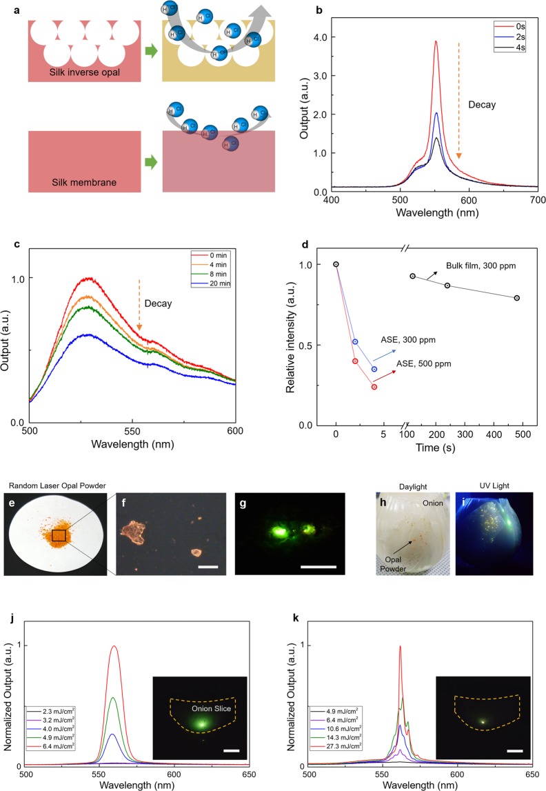
Figure 5.
Applications of the SIO light source. (a) A schematic diagram to show the working principle of chemosensing by the SIO. The large surface-to-the-volume ratio and light amplification of the SIO make it possible to obtain highly efficient chemosensors. (b) Time-dependent ASE spectrum changes of the SIO exposed to HCl vapor with a 300-ppm concentration. (c) Time-dependent fluorescence changes of the bulk silk/dye film. The HCl vapor had a 300-ppm concentration. (d) The relative output intensities of the PL as a function of the exposure time. (e–g) Photograph and microscopic images of the SIO powder. The image in g shows RL from an SIO sub-mm particle under the pump fluence. Scale bars in (f,g) indicate 500 μm. (h,i) Photograph images of the SIO particles integrated under the cover tissue of an onion in daylight (h) and ultraviolet (UV) light (i). Bright PL spots of the SIO are revealed under the UV excitation. (j,k) ASE and RL spectra obtained from the integrated SIO particle. Insets are far-field CCD images showing the ASE and RL from the particle. Scale bars indicate 1 cm.

