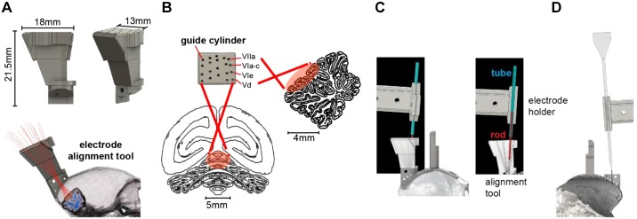
Fig. 3.
Design of the electrode trajectory guidance tool. A: the alignment tool was designed to allow precise placement of the electrode along each of the 20 desired trajectories that converged onto various cerebellar destinations. The tool consisted of a 3-dimensionally (3D) printed block (2.03 g) that had a single cylinder for each of the desired electrode trajectories. Shown is a model of the tool with 20 guide cylinders that align with the recording regions of interest and converge through the single craniotomy burr hole. B: guide cylinder trajectories with posterior and sagittal views of the recording range on the cerebellum. Labels identify the cerebellar lobule that the trajectory is aimed toward. C: alignment of the electrode with the desired trajectory. We installed the alignment tool in the base chamber and then placed a rod in the cylinder corresponding to the desired trajectory (image at right shows a section view of the alignment tool). We then placed a tube in the electrode holder (the same holder that would later hold the electrode) and attached the electrode holder to the microdrive. The microdrive was then maneuvered by a micromanipulator so that the axis of motion of the microdrive holding the tube was aligned with the rod. D: an image of the electrode and the electrode holder aligned to advance along the desired trajectory.

