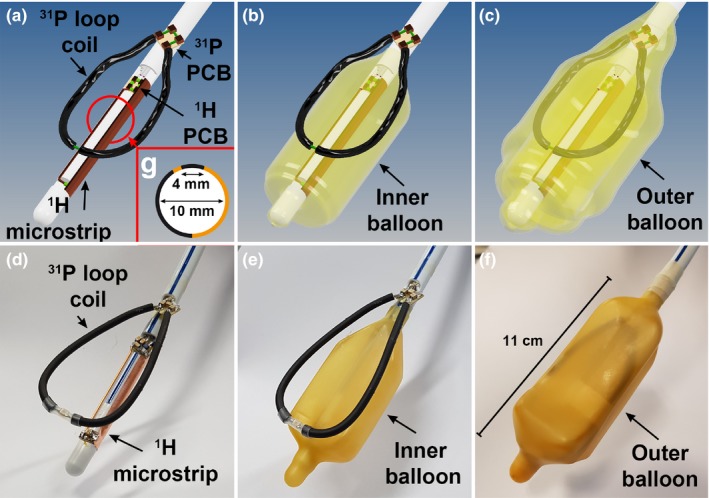
Figure 1.

3D drawings of the endorectal coil without any balloon (a), with the inner balloon (b) and with the inner and outer balloon present (c). The 31P Tx/Rx loop is positioned between the balloons while the 1H Rx elements is attached to the rod inside the inner balloon. The corresponding photos of the actual coil are depicted in d, e, and f. A schematic cross section of the asymmetric 1H microstrip (g) shows its orientation and geometry. The copper colored (online version only) parts indicate the conducting line and ground plane. [Color figure can be viewed at http://www.wileyonlinelibrary.com]
