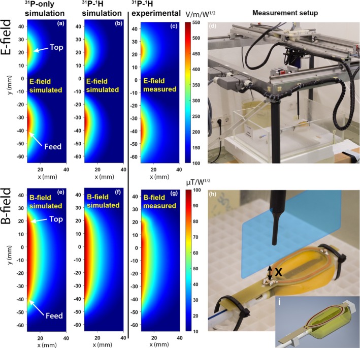
Figure 3.

Electromagnetic field simulations of the 31P loop coil in transmit mode of the 31P‐only (E‐field: a, B‐field: e) and the 31P/1H (E‐field: b, B‐field: f) ERC. The corresponding experimental measurements of the 31P/1H ERC (E‐field: c, B‐field: g) are shown as well. An overview image (d) and a picture of the modified PCB coil (h) show the measurement setup and the sagittal plane (blue (online version only) plane) that was used to perform the measurements. The 3D model used for the simulations is shown in (i). X indicates the distance from the conductors in mm. Both the simulations and measurements were performed within the same plane. The feed of the coil was positioned at the bottom of the E‐ and B‐field maps, and the top of the coil was positioned at the top of the maps. For the actual measurements, the transparent box (d) containing the coil was filled with tissue simulating fluid and the loop was covered with a balloon. ERC, endorectal radiofrequency coil. [Color figure can be viewed at http://www.wileyonlinelibrary.com]
