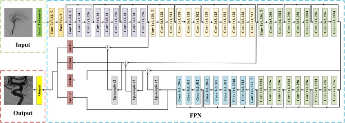
Fig. 9.
The architecture of region localization stage (RLS). In this figure, ‘’ denoted convolutional layer with size of filters f, and number of channels c and strides s (default strides was 1). Noting that each Conv layer was followed by a BN and an activation layer of ReLU. ‘’ meant max pooling layer whose size of filters f and strides s. ‘’ indicated nearest neighbor up-sampling with up-sampling rate r. ‘Anchor’ was anchor box which was utilized to predict the PCoA region. The first part was an input receiving a three-channel RGB image. The following feature extraction block was FPN with backbone of ResNet50. At last, the anchor boxes output the PCoA region of original input image

