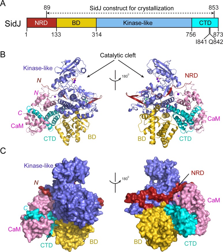
Figure 2. Overall structure of the SidJ–CaM complex.
(A) Schematic diagram of SidJ domain architecture. SidJ is comprised of a N-terminal regulatory domain (NRD) in red, a base domain (BD) in yellow, a kinase-like catalytic domain in blue, and a C-terminal domain (CTD) in cyan. The construct used for crystallography (89–853) is depicted above the schematic. (B) Overall structure of SidJ bound to CaM in a cartoon representation. SidJ structure is colored with the same scheme as in (A) and CaM is colored in pink. Ca2+ ions are depicted as purple spheres. The kinase-like domain of SidJ has a bilobed structure with two Ca2+ ions and a pyrophosphate molecule bound at the catalytic cleft between the two lobes. The right panel is a 180° rotation of the left panel and depicts the NRD domain contacts with CaM. (C) Molecular surface representation of SidJ bound to CaM in the same orientation and coloring as in (B). The right panel is a 180° rotation of the left panel. Note that the NRD meanders on the surface of the kinase-like domain and mediates the contact between the kinase-like domain and CaM.
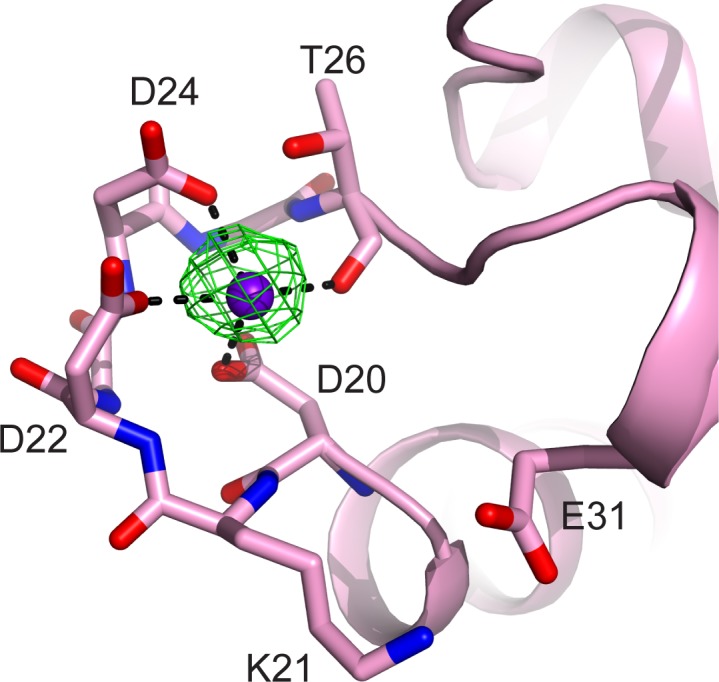
Figure 2—figure supplement 1. CaM EF-hand coordinated with one Ca2+.


