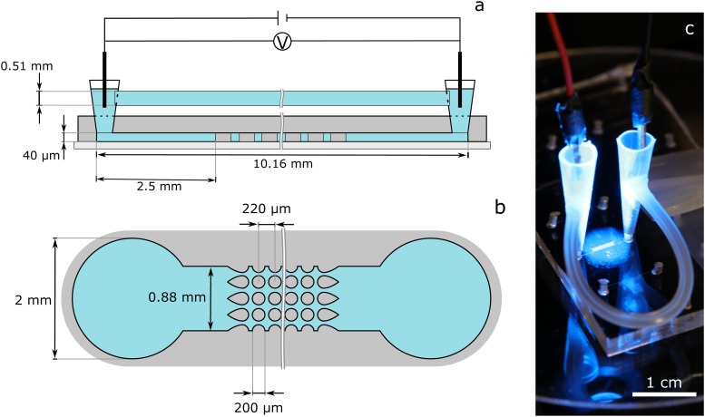
FIG. 3.
(a) Schematic representation (side view, not to scale) of a microchannel with post array (figure based on Ref. 16). Two pipette tips were inserted into holes that were previously punched into the PDMS to serve as fluid reservoirs. The reservoirs were connected to each other by a tube in order to balance the static pressure that builds up in the reservoirs during experiments. An electric field is applied across the channel length by introducing two platinum wires into the reservoirs. (b) Schematic sketch of the channel (top view, not to scale). The used post array consists of cylindrical isolating posts in a square array of posts with “dove-tail” geometry at the inlet and outlet. (c) Photo of the microchannel with reservoir connection tube and electrodes.

