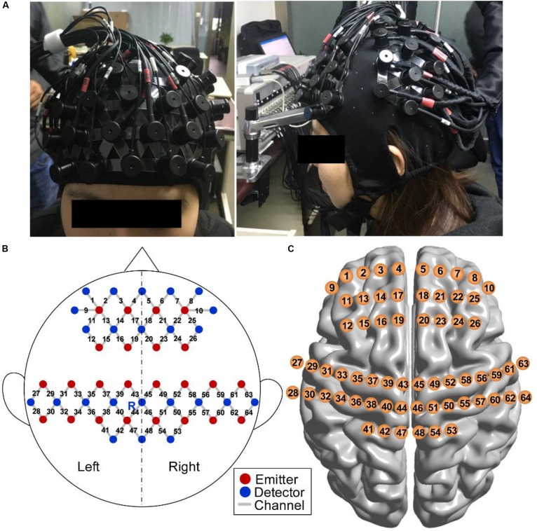
FIGURE 5.
fNIRS measurement. (A) Photograph of fNIRS measurement on a participant. (B) Schematic of imaging pad. Twenty-two emitters (red dots) and 24 detectors (blue dots) were symmetrically placed on the bilateral hemispheres and constituted 64 measurement channels (gray lines), allowing for the prefrontal and sensorimotor cortices to be measured. The emitter R was placed in Cz of the international 10–20 system. (C) Anatomical position of each measurement channel.

