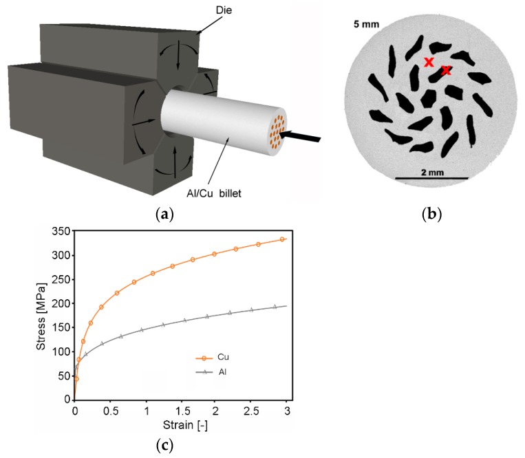
Figure 1.
Schematic depiction of rotary swaging setup of Al/Cu composite (a); cross-sectional cut of 5 mm 20C swaged composite, with locations for structure analyses at approximately mid-radius for both components, marked with “x”; (b) stress–strain curves for individual metals used for numerical prediction (c).

