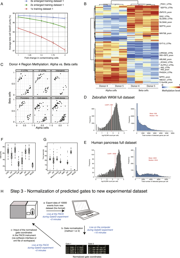
Figure S7.
α and β Cells Purified with GateID Can Be Used for Methylome Analysis, Related to Figure 6
(A) Average beta cell purity depending on TD size and proportion of contaminating cells in the TD. The y axis denotes the average GateID purity and its standard deviation. The x axis represents the fold change of the proportion of the contaminating cells in the TD. The curves represent different datasets: 1x is the original pancreas TD1 (678 cells), while 2x and 3x datasets are enlarged by two (1356 cells) or three (2034 cells) fold, respectively.
(B) Hierarchical clustering of mean methylation values for differentially methylated bins from the most variable bins, wherein methylation is shown in a gradient from blue (low) to red (high). Methylation in pancreatic alpha and beta cells cluster by cell type instead of donor of origin (indicated in columns). Bins with annotated genes of interest (rows) are shown on the right.
(C) Bins used in (D) were annotated and grouped by their genomic features for donor 4, wherein each point represents an average methylation value for a certain bin. Average methylation from alpha cells is shown on the x axis while y axis represents beta cells.
(D and E) Histogram of UMI counts and number of detected genes per cell for (D) zebrafish WKM full dataset and (E) human pancreas full dataset.
(F) Purity estimate for 100 samples of gate optimization for a pair of gates using different optimization algorithms. The figure shows that MA-LS-Chains shows the best purity in comparison to 8 different optimization algorithms used here.
(G) Time (in seconds) 100 samples of gate optimization for a pair of gates using different optimization algorithms. NMK and BOQA algorithms are fast but at the cost of substandard solution for the gate prediction problem.
(H) Workflow of the normalization of GateID predicted gates to a new experimental dataset. In step a, the data of 10000 events is exported live from the FACS machine to a laptop. In step b, the GateID gates are normalized leading to normalized gate coordinates (for each gate vertex (rows) the x and y gate coordinates are printed). Finally, in step c, the normalized gate coordinated are imported back into the FACS instrument via a software interface or the XML file of the workspace).

