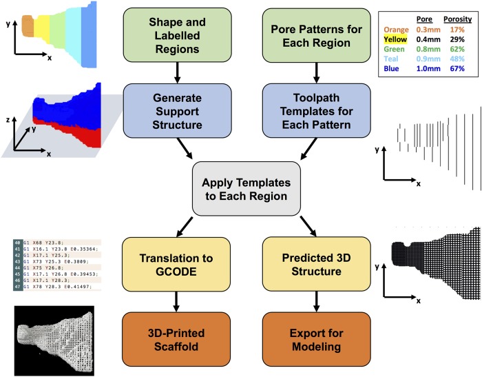
Fig 1. Overview of scafSLICR approach.
User inputs a labeled 3D shaped and the pore properties for each label (green boxes). The program then generates a support structure between the shape and the print bed (blue/red shape) and tool path templates for each pore pattern (blue boxes). The slicing process convolves these tool path templates with each x-y level of the shape according to the label (gray box). The result of this convolution is then translated into a set of GCODE instructions or into a predicted porous model of the shape (yellow boxes). These outputs can be manufactured on a 3D-printer or used for in silico modeling (orange boxes).

