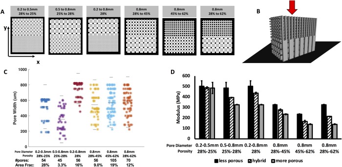
Fig 4. 3D-printed scaffolds with hybrid pore structures.
(A) 3D previews of scaffold designs featuring a more porous region and less porous region which meet at a center boundary. View is top-down onto the xy surface of the scaffold (B) Schematic showing application of force (red arrow) and alignment of scaffold on the platen (black plane) (C) Pore connectivity of transition plane: measured pore areas, number of pores, and area fraction of boundary plane that is connected pore space. Gray lines indicate median and upper and lower quartiles. (D) The compressive modulus of each transition scaffold compared to homogenous scaffolds composed of one of the pore diameter-porosity combinations found in the transition scaffold.

