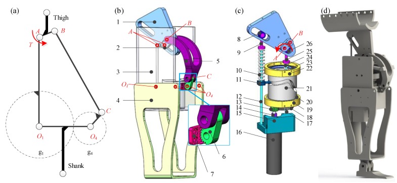
Figure 1.
(a) Schematic diagram, (b) structure, (c) actuation mechanism, and (d) CAD model of the GFB prosthetic knee. 1-level arm (fixed on linkage ), 2-linkage (thigh linkage), 3-linkage (frame), 4-linkage (shank linkage), 5-linkage , 6-linkage (incomplete gear centered at hinge ), 7-incomplete gear (fixed on linkage ), 8-bearing, 9-spring fastening, 10-helical spring, 11-cam roller, 12-guide, 13-transmission gear, 14-coupling, 15-motor cabinet (fixed on frame), 16-motor, 17-guide, 18-transmission gear, 19-bearing chock, 20-bearing, 21-cylindrical conjugate cams (two cam grooves on outer/inner walls of the cylinder), 22-bearing chock, 23-bearing, 24-helical spring, 25-spring fastening, 26-bearing.

