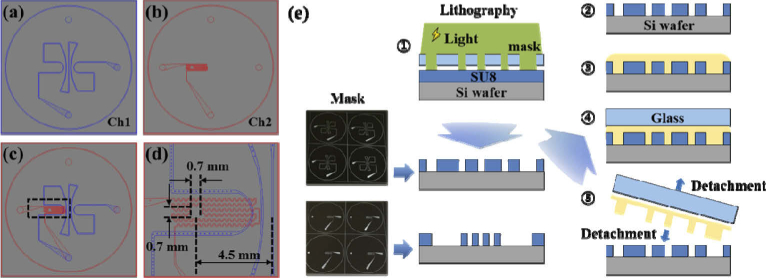
Fig. 3.
Design of the microfluidic channels and illustration of processing steps of the microfluidic channels. (a) Ch1 mimicked superficial vessels which were designed to spread from the center to the edge like the optic disc area. The widths of the channels ranged from 100 to 200 µm. (b) Ch2 mimicked deep vessels. The widths of the channels were designed to be 50 µm. (c) Overlapped drawings of Ch1 and Ch2. (d) Enlarged drawing of the area highlighted by the black square of Fig. 3(c). An empty space with an area of 0.7 mm × 0.7 mm mimicked the avascular zone of the fovea that was located 4.5 mm away from the center. (e) Processing step of the microfluidic channels with a microfluidic technique: Steps 1 and 2: Two molds for microfluidic channels are patterned in two Si wafers using photo-lithographic processes. Step 3: The mixture which consists of PDMS, TiO2 and curing agent is poured onto each mold. Step 4: A silane coated glass is placed on the mixture to provide pressure. Step 5: After curing, the microfluidic channel layer is detached from the mold and glass.

