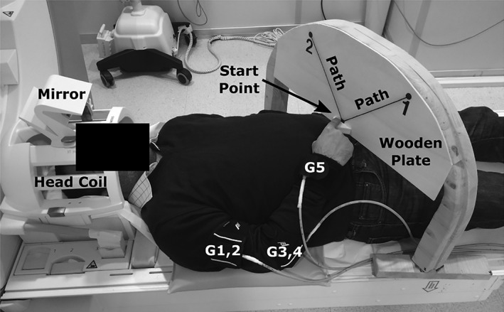
Figure 1.

Experimental setup. Targets were shown by “1” and “2” on the wooden plate at the end of the instructed movement paths differing with 90°. G1–5 illustrate the movement tracking gyroscopes mounted on the arm for capturing the kinematics of arm movements
