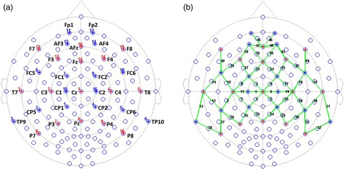
Figure 2.

Locations of optodes and channels with respect to the EEG 10/10 system. (a) Sixteen LED emitters were placed on positions F7‐F8, F3‐F4, T7‐T8, C3‐C4, P7‐P8, P3‐P4, AFz, Fz, Cz, and Pz (red dots), while sixteen detectors were placed on Fp1‐Fp2, AF3‐AF4, FC5‐FC6, FC1‐FC2, C1‐C2, TP9‐TP10, CP5‐CP6, and CP1‐CP2 (blue dots). (b) the 16 × 16 optodes constitute 48 channels of interest (green lines) [Color figure can be viewed at http://wileyonlinelibrary.com]
