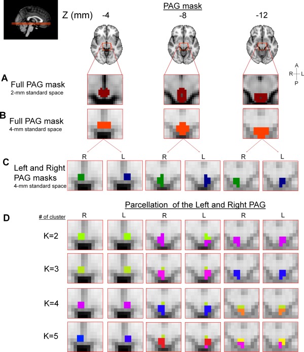
Figure 2.

(A) Full PAG mask as drawn in 2 mm3 MNI space. (B) Full PAG mask transformed to 4 mm3 MNI space. (C) 4 mm3 standard space masks used for the PAG parcellation (right and left, 15 4 × 4 × 4 voxels each). (D) Parcellation of the right and left PAG into 2–5 clusters (using K = 2–5) projected onto on 3 axial slices (left panel, MNI152, Z = −12, −8, and −4). Different colors represent the different clusters. R: right; L: left; A: anterior; P: posterior.
