Abstract
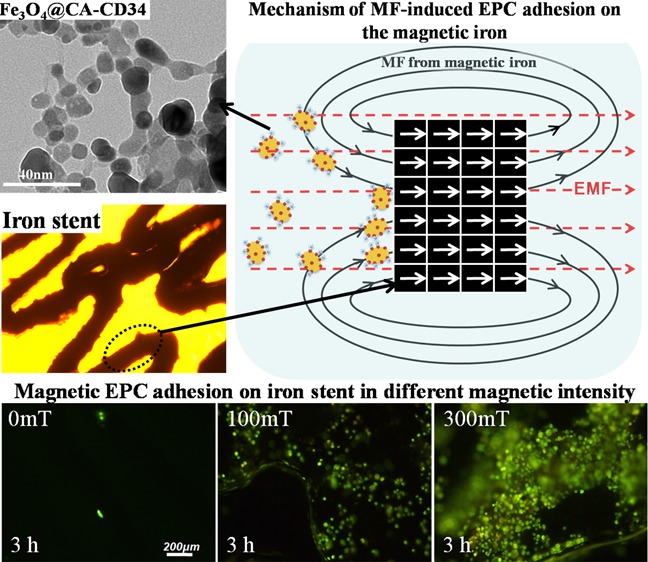
Iron stents, with superior mechanical properties and controllable degradation behavior, have potential for use as feasible substitutes for nondegradable stents in the treatment of coronary artery occlusion. However, corrosion renders the iron surface hard to modify with biological molecules to accelerate endothelialization and solve restenosis. The objective of this study is to demonstrate the feasibility of using endothelial progenitor cells (EPCs) to rapidly adhere onto iron surfaces with the assistance of anti-CD34-modified magnetic nanoparticles. Transmission electron microscopy, Fourier transform infrared spectroscopy, Thermogravimetric analysis, XRD, and anti-CD34 immunofluorescence suggested that anti-CD34 and citric acid were successfully modified onto Fe3O4, and Prussian blue staining demonstrated the selectivity of the as-prepared nanoparticles for EPCs. Under an external magnetic field (EMF), numerous nanoparticles or EPCs attached onto the surface of iron pieces, particularly the side of the iron pieces exposed to flow conditions, because iron could be magnetized under the EMF, and the magnetized iron has an edge effect. However, the uniform adhesion of EPCs on the iron stent was completed because of the weakening edge effect, and the sum of adherent EPCs was closely linked with the magnetic field (MF) intensity, which was validated by the complete covering of EPCs on the iron stent upon exposure to a 300 mT EMF within 3 h, whereas almost no cells were observed on the iron stent without an EMF. These results verify that this method can efficiently promote EPC capture and endothelialization of iron stents.
Introduction
Cardiovascular stents were first introduced for the therapy of coronary artery obstructions in the late 1980s. To date, stents have been widely applied in various locations within the vascular system and have proven their effectiveness in treating narrow arteries.1 Limited by the clinical duration of the stent, the interventional effect should be temporary, yet 6–12 months are demanded for the whole process of healing and re-endothelialization.2 Beyond the short intervention time, the stents impede the lumen stretching and contraction associated with later favorable remodeling and vessel reactivity where the stent is placed, making this site a latent nidus for thrombosis, restenosis, and chronic inflammation.3 Therefore, researchers suggest that degradable stents should possess long-term effects and that the desired degradation time should be within 12–24 months.4 In addition, when used in growing children, a standard stent requires redilatation after a few years to avoid fixed obstruction of the growing vessel.5 Thus, excluding emergency situations, stents for pediatric patients should not be applied if the maximal diameter of the stent could not satisfy the matching requirements for an adult vessel size. Degradable stents allow alternative therapeutic strategies,6 which have the potential to heal arterial vessels to prevent late stent thrombosis and in-stent restenosis3 via suspending the interference of the stents to the vessel wall, and may be used to clinically treat congenital heart disease in babies7 to avoid surgical intervention for redilatation and critical limb ischemia in adults.8 Another advantage of degradable stents is that they will not hinder any subsequent surgery at the target vessel.9
Because its mechanical properties are superior to those of 316L stainless steel (316L SS), iron has potentially valuable application for use in degradable stents and is considered more suitable than Mg alloys and polymers.10 Iron stents (Fe > 99.8%) were implanted in the descending aorta of animals11−14 and showed favorable biological performances,15 while the degradation period was considered too long for stent applications14 because the strut of the iron stent did not disappear completely within 18 months.11 For this reason, great focus has been placed on accelerating the degradation of iron-based stents.16−18 Based on the analyses of the intimal thickness and area as well as occlusion rate, iron stents do not have an advantage over 316L SS or cobalt chromium stents, although they have been shown to be safe in some studies. For example, the degrees of narrowings of the luminal area of cobalt chromium stents and iron stents were ∼41 and 34%, respectively, after 28 days of implantation,13 and the degrees of narrowings of the luminal area of 316L SS stents and iron stents were ∼36 and 40%, respectively, after 60 days of implantation.12 There were obvious developments of in-stent restenosis for all of the metals.
Restenosis is a direct result of the vessel injury during balloon angioplasty and coronary stenting. Vessel injury, which induces persistent disturbance and delayed endothelial monolayer recovery, will result in fibrin deposition, inflammatory cell infiltration, and subsequent neointima formation and vascular remodeling, which is the final trigger of lumen occlusion.19 To prevent restenosis and stent thrombosis, a functional endothelium should be established as soon as possible after stent implantation.20,21 Because of the promising benefits of circulating endothelial progenitor cells (EPCs) in vascular re-endothelialization after carotid balloon injury and neovascularization during post-ischemic inflammation,22 the surface of the implanted blood-contacting biomedical devices was designed to capture EPCs directly from the blood for in vivo/in situ endothelialization. Anti-CD34, anti-CD133, or anti-CD31 antibodies were immobilized on the surface of the devices via physical adsorption, electrostatic interaction, or covalent immobilization to attract EPCs for rapid endothelialization.23−26 More importantly, anti-CD34 antibody has been grafted onto a cardiovascular stent (Genous R-stent) to capture the EPC in the blood to accelerate endothelialization,24 demonstrating the safety and feasibility of this method. Nevertheless, one of the complexities is that corrosion is the major obstacle preventing modification of iron surfaces with biomolecules to accelerate endothelialization.
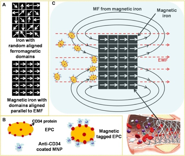
Some studies have shown that cells magnetically tagged by endocytosis of superparamagnetic nanoparticles (MNPs) were homed to a site of arterial injury27,28 and were rapidly captured onto a magnetic SS or magnesium stent using an external magnetic field (EMF) positioned outside the body.29−32 The saturation magnetization (Ms) of these metals is below 10 emu/g, which is far lower than that of iron (217 emu/g);30 therefore, magnetization of iron (Figure 1A), in theory, could exhibit an excellent response to an EMF and then enhance the surrounding magnetic field (MF) intensity under the same EMF. We hypothesized that via magnetic-related mechanisms, EPCs, which are specifically tagged with MNPs (Figure 1B), could be guided to the magnetic iron stent for re-endothelization. Compared to an isolated EMF, the magnetic-field intensity around a stent might increase in the presence of iron by superimposing the EMF and the responsive field of the magnetizing iron stent, making it possible to maximize the fraction of captured MNP-tagged cells by these techniques (Figure 1C).
Figure 1.
(A) Because of ferromagnetism, magnetization under an EMF converts ferromagnetic domains in iron from a random arrangement to be parallel to the EMF. (B) Schematic diagram of EPCs expressing the CD34 membrane protein and anti-CD34-coated MNPs and EPCs magnetically tagged by anti-CD34-coated MNPs. (C) Superimposition of the EMF and the responsive field of the magnetizing iron enables the iron stent to magnify the surrounding MF intensity and augment the quantity of captured MNP-tagged EPCs for rapid endothelialization.
To examine this concept experimentally, we first formulated and characterized anti-CD34 antibodies (anti-CD34)- and citric acid (CA)-conjugated Fe3O4 that could target EPCs and proceeded to identify optimal MNP cell-loading conditions with respect to MNP usage. Ultimately, the possibility of in vitro delivering of EPCs to the surfaces of iron stents was assessed in a model flow-loop system in the presence of MNPs and an EMF by using paired permanent magnets.
Results and Discussion
Characterization of MNPs
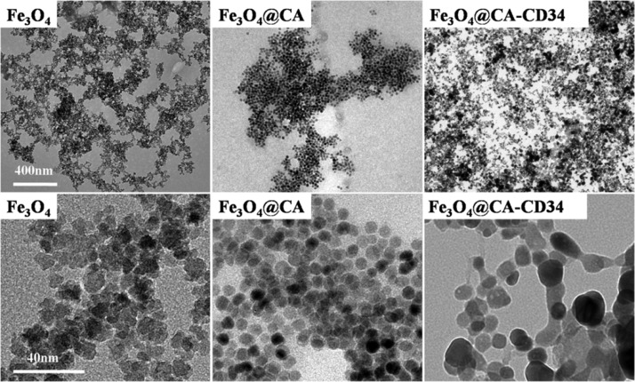
Transmission electron microscopy (TEM) micrographs of Fe3O4, Fe3O4@CA, and Fe3O4@CA–CD34 are shown in Figure 2. Fe3O4 has a more angular morphology with a size of approximately 10–20 nm and tended to aggregate. Fe3O4@CA was uniformly round with diameters of approximately 10 nm without aggregation, while the morphology of Fe3O4@CA–CD34 was irregularly shaped and elongated with lengths from 20 to 60 nm. These results demonstrate that CA and anti-CD34 antibody were successfully modified onto Fe3O4, while grafting with antibodies caused cross-linking of the MNPs. The size of MNPs for in vivo applications must be smaller than 200 nm to avoid filtration in the spleen and larger than 5 nm to avoid renal clearance.33,34 A longer half-life in vivo has been substantiated for nanoparticles with elongated shapes (e.g., filamentous35 or nanoworm36) compared with nanospheres. Therefore, Fe3O4@CA–CD34 has been considered suitable for in vivo applications.
Figure 2.
TEM micrographs of Fe3O4, Fe3O4@CA, and Fe3O4@CA–CD34.
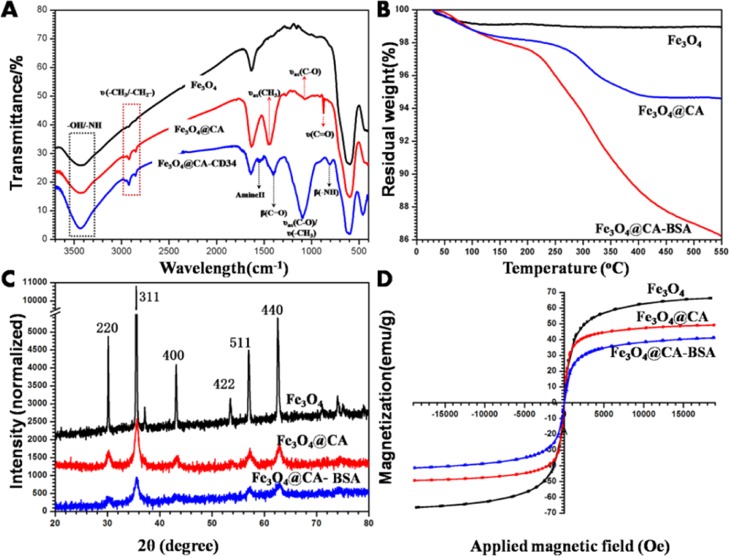
Further analysis was performed by means of IR spectroscopy. Figure 3A shows the IR spectrum of the different MNPs dispersed in KBr. The band at 596 cm–1 corresponds to Fe–O vibrations, indicating that Fe3O4 was successfully prepared. Compared with the Fe3O4 spectrum, the spectrum obtained after the addition of CA exhibited new peaks at 2980/1446, 2930, 1072, and 873 cm–1 that correspond to the stretching vibration of CH3, CH2, C–O, and C=O, respectively, demonstrating that CA has bonded to the surface of Fe3O4. Compared with the Fe3O4@CA spectrum, the spectrum obtained after the addition of anti-CD34 antibody exhibited new peaks at 1546, 1398, and 808 cm–1 attributed to amide II vibrations and bending vibrations of C–O and N–H, respectively, which illustrated the successful immobilization of anti-CD34 antibody onto the Fe3O4@CA surface. An intense characteristic absorption peak at 1095 cm–1 was attributed to C–O and CH3 stretching, also indicating that Fe3O4@CA–CD34 were successfully manufactured.
Figure 3.
(A) FTIR spectra of Fe3O4, Fe3O4@CA, and Fe3O4@CA–CD34. TGA analysis (B), XRD spectra (C) and magnetic hysteresis loops (D) of different kinds of Fe3O4, Fe3O4@CA, and Fe3O4@CA–BSA (because of its high price, anti-CD34 antibody was replaced by BSA in these analysis).
Thermogravimetric analysis (TGA) in a temperature range of 30–550 °C was used to investigate the thermal decomposition processes of Fe3O4, Fe3O4@CA, and Fe3O4@CA–BSA to quantitatively analyze the proportion of CA and protein in the MNPs. The TGA curve of Fe3O4 in Figure 3B reveals a small weight loss rate of approximately 1% due to the evaporation of water at 40–90 °C, which is in accordance with our previous study.37 The weight loss rate of Fe3O4@CA was greater than that of Fe3O4, with a value of 5%, which contributed to the decomposition of CA. The decomposition temperature of free CA is 175 °C, but the initial decomposition temperature CA in Fe3O4@CA was 250 °C, indirectly indicating the interaction between CA and Fe3O4. A continuous weight loss occurred in Fe3O4@CA–BSA and reached 14% due to the removal of CA and bovine serum albumin (BSA). These results demonstrate that CA and protein have been modified onto nanoparticles. Compared with the linking of protein to Fe3O4 with PEG4000 in our previous study,37 the amount of the modified protein in this research decreased by approximately 5%, the reason for which is that the high molecular weight of poly(ethylene glycol) (PEG) leads to a larger surface area for protein immobilization.
XRD measurements were used to identify the crystalline structure of all MNPs in the dried powder phase. As shown in Figure 3C, all the observed diffraction peaks in the XRD patterns match well with the characteristic peaks of the inverse cubic spinel structure (JCPDS 19-0629), indicating that CA and protein did not influence the crystalline phase purity of Fe3O4. However, broadening and weakening of the characteristic diffraction peaks was observed in the CA-modified nanoparticles, indicating that this additive could constrain the crystal growth, causing the small crystallite size because CA with large numbers of COOH could easily chelate the iron from Fe3O4.38 The protein was grafted onto nanoparticles by CA, and as a consequence, this step did not lead to dramatic changes in the diffraction peaks as in our previous study.37
Magnetic hysteresis loops of Fe3O4, Fe3O4@CA, and Fe3O4@CA–BSA at room temperature were measured with the MF swept back and forth between +18 and −18 kOe. As seen in Figure 3D, the typical characteristics of superparamagnetic behavior (no hysteresis behavior) was observed showing almost immeasurable coercivity and remanence, which demonstrated that these nanoparticles possess superparamagnetic properties. The Ms values obtained from the plot are 66.3, 49.3, and 41.0 emu/g for Fe3O4, Fe3O4@CA, and Fe3O4@CA–BSA, respectively. These results proved that the CA and protein have been integrated into nanoparticles.
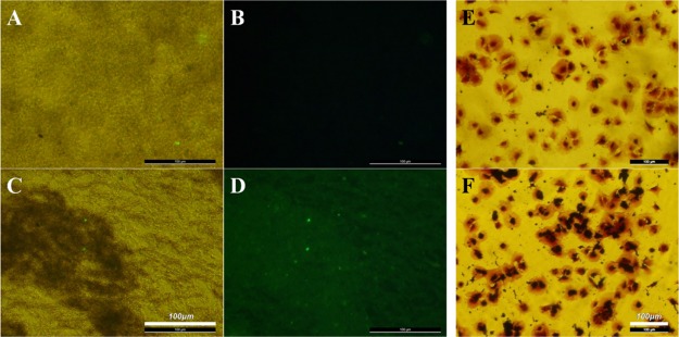
Immunofluorescent staining was used to evaluate the anti-CD34 antibody grafting by treating different nanoparticles with FITC-conjugated rabbit anti-goat IgG. The bright-field microscopy images showed that Fe3O4@CA (Figure 4A) and Fe3O4@CA–CD34 (Figure 4C) dispersed in water; furthermore, immunofluorescence images corresponding to the bright-field images showed strong fluorescence for Fe3O4@CA–CD34 (Figure 4D) and little immunofluorescence for Fe3O4@CA (Figure 4B), indicating that the anti-CD34 antibody was grafted onto CA-coated Fe3O4.
Figure 4.
Bright-field microscopy (A) and immunofluorescence (B) images of Fe3O4@CA, and the bright-field microscopy (C) and immunofluorescence (D) images of Fe3O4@CA–CD34. EPCs were incubated with Fe3O4@CA (E) and Fe3O4@CA–CD34 (F), and then cellular labeling was visualized histochemically with prussian blue (PB) staining, which indicated that anti-CD34-coated MNPs have selective affinity to EPCs.
Affinity of MNPs to EPCs
To evaluate the selective affinity of Fe3O4@CA–CD34 for EPCs, adherent EPCs were incubated with Fe3O4@CA and Fe3O4@CA–CD34 for 5 min, the iron closely bonded on the cells was stained with PB, and the cells were counterstained with crystal violet. The results showed that almost all EPCs incubated with Fe3O4@CA–CD34 exhibited positive iron staining (black) on the membrane (Figure 4E), but only a few of cells incubated with Fe3O4@CA exhibited positive iron staining (Figure 4F), indicating that Fe3O4@CA–CD34 has selective affinity for EPCs.
Cell Viability at Different MNP Concentrations
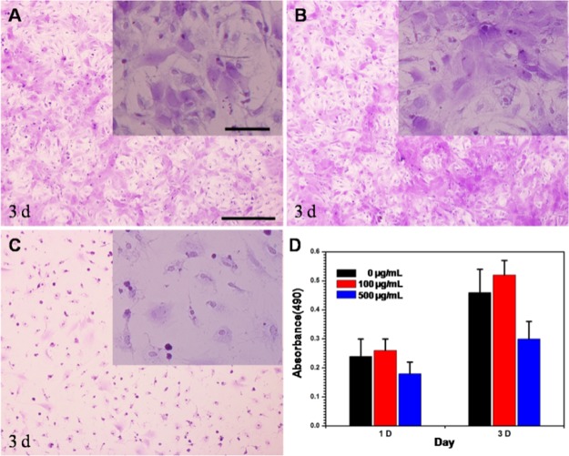
The influence of different concentrations of Fe3O4@CA–CD34 on the viability of EPCs needs to be investigated. Figure 5 shows that there was no difference in the cell morphology between EPCs without incubation with nanoparticles (Figure 5A) and EPCs incubated with nanoparticles at a concentration of 100 μg/mL (Figure 5B). Meanwhile, there were no significant differences in cell viability of two groups (Figure 5D). However, the number and morphology of cells incubated with nanoparticles at a concentration of 500 μg/mL (Figure 5C) were inferior to those of the other groups, and the viability of EPCs incubated with Fe3O4@CA–CD34 at a concentration of 500 μg/mL (Figure 5D) was significantly lower than that of the others, indicating that Fe3O4@CA–CD34 have significant cytotoxicity in high concentrations. Thus, the concentration of nanoparticles for capturing EPCs was set to 100 μg/mL.
Figure 5.
Microphotographs of the EPCs incubated with different concentrations of Fe3O4@CA–CD34 [(A) 0 μg/mL; (B) 100 μg/mL; (C) 500 μg/mL] for 3 days. Cell viability of the EPCs incubated with the different concentration of Fe3O4@CA–CD34 for 1 and 3 d (D).
Capturing Ability of Iron to MNPs
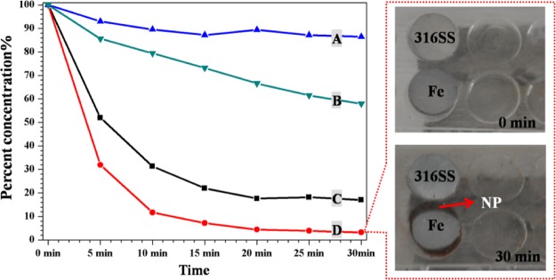
Because of its ferromagnetic properties, iron can increase the MF intensity of its surroundings by magnetization. To test this statement, an MNP suspension was pumped through a circular tube system with or without an iron piece under different EMFs. The remaining MNP concentration in the suspension was determined by inductively coupled plasma optical emission spectrometry (ICP-OES) and is presented in Figure 6. The residual MNP concentrations in the system without an iron piece were 20% at an EMF of 300 mT (C) and 90% at an EMF of 100 mT (A) after 30 min, confirming the dependence on the field strength. The presence of iron under the same EMF increased the MF intensity around the iron and caused a further depletion of the MNP suspension [300 mT: 20% without iron (C) vs 4% with iron (D); 100 mT: 90% without iron (A) vs 65% with iron (B)]. Thus, a high MF intensity can capture more MNPs, and iron can be magnetized to increase the surrounding MF intensity. Under the same EMF, MNPs were captured onto the iron surface but not onto 316L SS, also indicating that there was a higher MF intensity around iron than around 316L SS because of the high magnetizability of iron.
Figure 6.
Residual concentration of the MNP suspension (Fe3O4@CA–CD34) in a circulating closed loop system at different time points (A): 100 mT without iron, (B): 100 mT with iron, (C): 300 mT without iron, and (D): 300 mT with iron (Left). Images of absorbed MNPs around the iron and 316L SS pieces after circulation for 30 min (right).
Capturing Ability of Iron Piece/Stent to Magnetic Tagged EPCs
To determine whether Fe3O4@CA–CD34 can capture and deliver EPCs onto iron in the presence of an applied EMF of 300 mT, the number of adherent cells on the different samples was used to estimate the ability of MNP to capture and deliver EPCs; representative images are shown in Figure 7. Without an EMF, few EPCs adhered onto the iron pieces, while many EPCs adhered onto the iron pieces in the presence of a 300 mT of EMF for 1 h. It is important to note that the side of the iron piece was completely covered by EPCs. These results indicated that the iron pieces were beneficial to capturing EPCs magnetically tagged by Fe3O4@CA–CD34 and that the edge effect of the side strengthened this capability.
Figure 7.
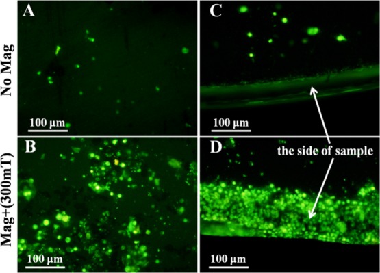
EPC adhesion onto the surface (A) and the side (C) of iron pieces assisted by anti-CD34-coated MNPs in the absence of an EMF and EPC adhesion onto the surface (B) and the side (D) of iron pieces assisted by anti-CD34-coated MNPs in the presence of a 300 mT EMF under flow conditions in vitro for 1 h.
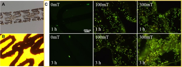
The EPC adhesion onto iron stents assisted by MNPs and an EMF under flow conditions in vitro was studied. For this, a suspension containing EPCs at a density of 5 × 10⁴/mL and Fe3O4@CA–CD34 at a concentration of 100 μg/mL were circulated in a closed flow chamber system at a flow rate of 1 m/s. Iron stents were placed into this system and exposed to EMFs of 100 and 300 mT for 1 and 3 h. The adherent cells were stained with rhodamine 123, and representative images are presented in Figure 8. The stereo-micrograph and bright-field image of the iron stent are shown in Figure 8A,B. Almost no cells were found on the surface of the stent after 1 and 3 h of circulation without EMF application (0 mT). However, an EMF of 100 or 300 mT was applied, the number of cells captured onto the iron stents significantly increased. At the same circulation times (1 or 3 h), an EMF of 300 mT caused more cells to adhere onto the stent than an EMF of 100 mT, indicating that the high MF intensity could accelerate EPC adhesion. Under an EMF of 100 mT, the number of cells captured onto the iron stents did not significantly increase with the circulation time, but the number of cells captured increased with the circulation time under an EMF of 300 mT, and the captured cells completely covered the iron stent after 3 h, indicating that a high magnetic-field intensity could accomplish EPC coverage within a short time.
Figure 8.
(A) Stereo-micrograph of the iron stent. (B) Bright-field image of the iron stent; (C) EPC adhesion onto iron stents assisted by Fe3O4@CA–CD34 and different EMF (0, 100 and 300 mT) for 1 and 3 h under flow conditions in vitro; cellular labeling was visualized histochemically with rhodamine 123 staining.
Our previous study proved that the anti-CD34 antibody and PEG-modified MNPs could target EPCs and then manipulate these EPCs into a specific position relative to an EMF in vivo.37 Compared EPC labeling with MNPs by endocytosis, anti-CD34 coated-MNPs are expected to be more applicable, particularly for patients requiring emergency procedures because they could avoid costly and time-consuming procedures, including the isolation and cultivation of EPCs under GMP conditions (2 weeks) and the labeling of EPCs with MNPs (16 h) in vitro.
The high magnetizability of iron allows rapid endothelialization of iron surfaces by the capture of magnetically tagged EPCs. The present study showed that many EPCs adhered onto iron pieces under an EMF of 300 mT for 1 h (Figure 7). Importantly, the edge effect of the magnetized iron causes the side of the iron piece to be completely covered by EPCs. The replacement of the iron piece by an iron stent reduced the edge effect, so that the EPCs magenetically tagged by Fe3O4@CA–CD34 entirely adhered onto the exterior of the iron stent within a short time. The number of captured EPCs on the iron stents increased with the intensity of the EMF under flow conditions in vitro (Figure 8), especially at a high MF intensity. Therefore, the magnetic properties of iron can be used to promote re-endothelialization in the presence of MNPs modified with anti-CD34 and exposed to an EMF. Unfortunately, accurate quantification of adherent EPCs was difficult to achieve because of the interference of MNPs and the corrosion of iron; additionally, the iron surface was corroded too quickly in the aqueous solution to acquire SEM images.
Conclusions
MNPs with a high affinity for EPCs were prepared by coating Fe3O4 with CA and anti-CD34 antibody. Magnetization of iron led to high adsorption of MNPs and magnetically tagged EPCs under an EMF. In contrast to massive iron (iron piece), linear iron (iron stent) results in the uniform adhesion of EPCs on the surface because of the weakened edge effect. The number of adherent EPCs on the iron stent was closely related to the EMF, and the whole surface of the iron stent was occupied by EPCs within 3 h in the presence of a 300 mT EMF. These results demonstrate that this method could efficiently promote EPC capture and endothelialization of iron stents.
Experimental Section
Preparation and Characterization of MNPs
CA-modified MNPs were prepared by a simple two-step co-precipitation method.38 In a typical reaction, 0.2 g of FeCl2·4H2O and 0.54 g of FeCl3·6H2O were mixed in 50 mL of deionized water for 10 min under nitrogen protection. While vigorously stirring the reaction mixture, ammonia solution was introduced dropwise until the pH was increased to 10, followed by the reaction for 1 h. The solution was heated to 80 °C for 30 min, and the product was denoted as Fe3O4. Then, 1 g of CA in 5 mL of water was added into the above solution with stirring for 2 h. CA-coated MNPs were separated by a permanent magnet and washed with water several times, and the product was denoted as Fe3O4@CA. Fe3O4@CA were ultrasonically dispersed in 30 mL of water containing 200 mg of MES, 10 mg of EDC, and 10 mg of NHS for 1 h at room temperature to activate the carboxyl groups, followed by separation by a permanent magnet and washing with 75% ethanol three times. The subsequent experiments were carried out under sterile conditions. The above MNPs were dispersed in 30 mL of sterile phosphate buffered solution (PBS, pH 7.4) containing anti-CD34 antibodies (specific for CD34 of humans, rats, cows, pigs, dogs, and rabbits) at 100 rpm for 6 h, separated by a permanent magnet, and then washed with sterile water several times. Anti-CD34 grafted MNPs were obtained and are denoted as Fe3O4@PEG–CD34.
The as-prepared MNPs were characterized by TEM, Fourier transform infrared spectroscopy (FTIR), TGA, X-ray powder diffraction (XRD), vibrating sample magnetometer (VSM), and immunofluorescent staining of the anti-CD34 antibody. TEM was used to obtain the sharp topography and size of MNPs by employing a JEM-2010 (JEOL, Japan) at an acceleration voltage of 80 kV in the bright field imaging mode. FTIR spectra of different MNPs prepared as KBr pellets were obtained using a ST-IR20SX (Nicolet, USA) to investigate the chemical bonding. Because of its high price, anti-CD34 antibody in Fe3O4@CA–CD34 is replaced by BSA in the analysis of TGA, XRD, and VSM. TGA of 15 mg of powder samples was measured on a NETZSCH STA449C (Jupiter, Germany) at a heating rate of 10 °C/min to 550 °C under a nitrogen atmosphere. XRD of different MNPs was recorded with a Philips X’Pert Pro diffractometer using Cu Kα (λ = 1.5406 Å) radiation. The magnetic hysteresis loop of MNPs was traced using the VSM (Lake Shore 7410, Lake Shore Cryotronics, America). Magnetization values were normalized to the mass of the nanoparticles to determine the specific magnetization (emu per gram of particles). The immunofluorescent identification of the anti-CD34 antibodies on the as-prepared MNPs was conducted as follows:39 MNPs were incubated with 1% BSA for 1 h and then removed by magnetic separation and re-suspended in water. FITC-conjugated rabbit anti-goat IgG (1:100) was incubated for 1 h in the stirring suspension (300 rpm), from which MNPs were collected by magnetic separation and washed three times with deionized water. The re-suspended MNPs were immediately observed via a fluorescence microscope (LEICA DMRX Polarization microscope, Leica Germany).
Affinity of MNPs to EPCs
As described previously, multipotential mesenchymal stem cells from femoral bone marrow were obtained from SD rats and cultured in Dulbecco’s modified Eagle’s medium (DMEM) culture medium containing 15% fetal calf serum, 10 ng/mL VEGF, 10 ng/mL SCF, penicillin (100 U/mL), and streptomycin sulfate (100 U/mL), at 37 °C under 5% CO2. The medium was renewed every 2–3 days, and the cells were subcultured regularly after they reached 70–80% confluence. Third-passage cells were characterized by immunofluorescent detection of CD34 membrane protein to prove the differentiation into EPCs.39
To study the ability of MNPs to target EPCs, the adherent EPCs in a 24-well plate were incubated with serum-free DMEM medium containing 100 μg/mL Fe3O4@CA and Fe3O4@CA–CD34, respectively. After 10 min of incubation, the medium was drawn off and the cells were washed with PBS to remove the nonadherent MNPs. Negative controls were prepared using the adherent EPCs without incubation with MNPs. Cells were fixed with 2.5% glutaraldehyde in PBS for 10 min and then washed three times with PBS. To visualize the iron in the MNP-labeled cells, PB staining was performed by incubating cells for 30 min with 2% potassium ferric–ferrocyanide (Perl reagent for PB staining) in 6% hydrochloric acid, and then the cells were washed and counterstained with crystal violet. Finally, the cells were observed for iron staining using light microscopy.
Cell Viability at Different MNP Concentration
A aliquot of 300 μL of the EPC suspension (5 × 10⁴/mL) was placed into a 24-well flat-bottomed plate to culture for 12 h for cell adhesion. Then, Fe3O4@CA–CD34 was added to co-culture with the cells, and the final concentrations of MNPs were 0, 100, or 500 μg/mL, respectively. After culturing for 3 d, the suspension was removed, and every well was washed five times with PBS. Then, adherent cells were stained with crystal violet and then observed using light microscopy. After culture for 1 and 3 d, the cell viability was assessed by MTT assay.
Capturing Ability of Iron to MNPs
The impact that the iron exerts on the capture ability of magnetic tagged EPCs is crucial to the analysis concerning whether this theoretical method of iron stent endothelialization can be applied in practice. Because of ferromagnetism, the surrounding MF intensity may increase because of the magnetization of iron. To verify this hypothesis, a solution of Fe3O4@CA–CD34 at a concentration of 100 μg/mL was circulated in a closed flow chamber system consisting of four basic modules: a parallel plate flow chamber, a flow loop with silicone catheter, a reservoir, and a peristaltic pump. Iron pieces were placed into the parallel plate flow chamber. The flow chamber with and without iron was exposed to the MF intensities of 100 or 300 mT, and then the solution in the reservoir was collected after circulation for different times. Then, the iron concentration in the collected solutions was detected by ICP-OES (SPECTRO ARCOS; AMETEK, Inc., Kleve, Germany). While 316L stainless steel (316L SS) and iron pieces were placed into the parallel plate flow chamber to observe the captured MNPs to evaluate the magnetizability of different samples.
Capturing Ability of Iron Piece/Stent to Magnetic Tagged EPCs
In an in vitro cell-capture experiment, an EPC suspension (5 × 10⁴/mL) and MNPs (100 μg/mL) were circulated in a closed flow chamber system at a flow rate of 1 m/s. Iron pieces were placed into the parallel plate flow chamber. The samples were exposed under an EMF of 300 mT for 1 h by paired permanent magnets placed at both sides of the samples. Samples without EMF served as control. After capturing, the samples were removed, washed with PBS, incubated with rhodamine 123 (20 μg/mL) for 15 min, and immediately observed under a fluorescence microscope.
In addition, iron stents were used to evaluate the magnetic-assisted EPC adhesion under flow conditions in vitro. An EPC suspension (5 × 10⁴/mL) and MNPs (100 μg/mL) circulated in a closed flow chamber system at a flow rate of 1 m/s. Iron stents were placed into the silicone catheter and exposed to an EMF of 100 and 300 mT for 1 and 3 h by paired permanent magnets placed at both sides of the stents. Stents without EMF served as a control. After circulation for different times, the stents were removed, washed with PBS, and incubated with rhodamine123 for 15 min and immediately observed under a fluorescence microscope.
Acknowledgments
This work was supported by the National Natural Science Foundation of China (no. 31670967), the Scientific Research Foundation of the Institute for Translational Medicine of Anhui Province (no. 2017zhyx19), the University Outstanding Youth Talent Support Program of Anhui Province (no. gxyq2018007), and the Postdoctoral Science Foundation of Anhui Province (no. 2018B264).
The authors declare no competing financial interest.
References
- Zaman A.; de Winter R. J.; Kogame N.; Chang C. C.; Modolo R.; Spitzer E.; Tonino P.; Hofma S.; Zurakowski A.; Smits P. C.; Prokopczuk J.; Moreno R.; Choudhury A.; Petrov I.; Cequier A.; Kukreja N.; Hoye A.; Iniguez A.; Ungi I.; Serra A.; Gil R. J.; Walsh S.; Tonev G.; Mathur A.; Merkely B.; Colombo A.; Ijsselmuiden S.; Soliman O.; Kaul U.; Onuma Y.; Serruys P. W. Safety and efficacy of a sirolimus-eluting coronary stent with ultra-thin strut for treatment of atherosclerotic lesions (TALENT): a prospective multicentre randomised controlled trial. Lancet 2019, 393, 987–997. 10.1016/s0140-6736(18)32467-x. [DOI] [PubMed] [Google Scholar]
- Boccafoschi F.; Fusaro L.; Cannas M.. 15-Immobilization of peptides on cardiovascular stent. In Functionalised Cardiovascular Stents; Wall J. G., Podbielska H., Wawrzyńska M., Eds.; Woodhead Publishing, 2018, pp 305–318. [Google Scholar]
- Waksman R. Update on bioabsorbable stents: from bench to clinical. J. Interv. Cardiol. 2006, 19, 414–421. 10.1111/j.1540-8183.2006.00187.x. [DOI] [PubMed] [Google Scholar]
- Serruys P. W.; Kutryk M. J. B.; Ong A. T. L. Coronary-artery stents. N. Engl. J. Med. 2006, 354, 483–495. 10.1056/nejmra051091. [DOI] [PubMed] [Google Scholar]
- McMahon C. J.; El-Said H. G.; Grifka R. G.; Fraley J. K.; Nihill M. R.; Mullins C. E. Redilation of endovascular stents in congenital heart disease: factors implicated in the development of restenosis and neointimal proliferation. J. Am. Coll. Cardiol. 2001, 38, 521–526. 10.1016/s0735-1097(01)01406-1. [DOI] [PubMed] [Google Scholar]
- Hu T.; Yang C.; Lin S.; Yu Q.; Wang G. Biodegradable stents for coronary artery disease treatment: Recent advances and future perspectives. Mater. Sci. Eng., C 2018, 91, 163–178. 10.1016/j.msec.2018.04.100. [DOI] [PubMed] [Google Scholar]
- Zartner P.; Buettner M.; Singer H.; Sigler M. First biodegradable metal stent in a child with congenital heart disease: Evaluation of macro and histopathology. Cathet. Cardiovasc. Interv. 2007, 69, 443–446. 10.1002/ccd.20828. [DOI] [PubMed] [Google Scholar]
- Peeters P.; Bosiers M.; Verbist J.; Deloose K.; Heublein B. Preliminary results after application of absorbable metal stents in patients with critical limb ischemia. J. Endovasc. Ther. 2005, 12, 1–5. 10.1583/04-1349r.1. [DOI] [PubMed] [Google Scholar]
- Kounis N. G.; Koniari I.; Roumeliotis A.; Tsigas G.; Soufras G.; Grapsas N.; Davlouros P.; Hahalis G. Thrombotic responses to coronary stents, bioresorbable scaffolds and the Kounis hypersensitivity-associated acute thrombotic syndrome. J. Thorac. Dis. 2017, 9, 1155–1164. 10.21037/jtd.2017.03.134. [DOI] [PMC free article] [PubMed] [Google Scholar]
- Hideo-Kajita A.; Wopperer S.; Seleme V. B.; Ribeiro M. H.; Campos C. M. The Development of Magnesium-Based Resorbable and Iron-Based Biocorrodible Metal Scaffold Technology and Biomedical Applications in Coronary Artery Disease Patients. Appl. Sci. 2019, 9, 3527. 10.3390/app9173527. [DOI] [Google Scholar]
- Peuster M.; Wohlsein P.; Brugmann M.; Ehlerding M.; Seidler K.; Fink C.; Brauer H.; Fischer A.; Hausdorf G. A novel approach to temporary stenting: degradable cardiovascular stents produced from corrodible metal---results 6-18 months after implantation into New Zealand white rabbits. Heart 2001, 86, 563–569. 10.1136/heart.86.5.563. [DOI] [PMC free article] [PubMed] [Google Scholar]
- Peuster M.; Hesse C.; Schloo T.; Fink C.; Beerbaum P.; von Schnakenburg C. Long-term biocompatibility of a corrodible peripheral iron stent in the porcine descending aorta. Biomaterials 2006, 27, 4955–4962. 10.1016/j.biomaterials.2006.05.029. [DOI] [PubMed] [Google Scholar]
- Waksman R.; Pakala R.; Baffour R.; Seabron R.; Hellinga D.; Tio F. O. Short-term effects of biocorrodible iron stents in porcine coronary arteries. J. Interv. Cardiol. 2008, 21, 15–20. 10.1111/j.1540-8183.2007.00319.x. [DOI] [PubMed] [Google Scholar]
- Zheng J.-F.; Qiu H.; Tian Y.; Hu X.-Y.; Luo T.; Wu C.; Tian Y.; Tang Y.; Song L.-F.; Li L.; Xu L.; Xu B.; Gao R.-L. Preclinical Evaluation of a Novel Sirolimus-Eluting Iron Bioresorbable Coronary Scaffold in Porcine Coronary Artery at 6 Months. JACC Cardiovasc. Interv. 2019, 12, 245–255. 10.1016/j.jcin.2018.10.. [DOI] [PubMed] [Google Scholar]
- Mueller P. P.; May T.; Perz A.; Hauser H.; Peuster M. Control of smooth muscle cell proliferation by ferrous iron. Biomaterials 2006, 27, 2193–2200. 10.1016/j.biomaterials.2005.10.042. [DOI] [PubMed] [Google Scholar]
- Moravej M.; Purnama A.; Fiset M.; Couet J.; Mantovani D. Electroformed pure iron as a new biomaterial for degradable stents: In vitro degradation and preliminary cell viability studies. Acta Biomater. 2010, 6, 1843–1851. 10.1016/j.actbio.2010.01.008. [DOI] [PubMed] [Google Scholar]
- Huang T.; Zheng Y.; Han Y. Accelerating degradation rate of pure iron by zinc ion implantation. Regener. Biomater. 2016, 3, 205–215. 10.1093/rb/rbw020. [DOI] [PMC free article] [PubMed] [Google Scholar]
- Qi Y.; Li X.; He Y.; Zhang D.; Ding J. Mechanism of Acceleration of Iron Corrosion by a Polylactide Coating. ACS Appl. Mater. Interfaces 2019, 11, 202–218. 10.1021/acsami.8b17125. [DOI] [PubMed] [Google Scholar]
- Sousa J. E.; Serruys P. W.; Costa M. A. New Frontiers in Cardiology. Circulation 2003, 107, 2274–2279. 10.1161/01.cir.0000069330.41022.90. [DOI] [PubMed] [Google Scholar]
- Kong D.; Melo L. G.; Mangi A. A.; Zhang L.; Lopez-Ilasaca M.; Perrella M. A.; Liew C. C.; Pratt R. E.; Dzau V. J. Enhanced inhibition of neointimal hyperplasia by genetically engineered endothelial progenitor cells. Circulation 2004, 109, 1769–1775. 10.1161/01.CIR.0000121732.85572.6F. [DOI] [PubMed] [Google Scholar]
- Li J.; Zhang K.; Huang N. Engineering Cardiovascular Implant Surfaces to Create a Vascular Endothelial Growth Microenvironment. Biotechnol. J. 2017, 12, 1600401. 10.1002/biot.201600401. [DOI] [PubMed] [Google Scholar]
- Asahara T.; Murohara T.; Sullivan A.; Silver M.; van der Zee R.; Li T.; Witzenbichler B.; Schatteman G.; Isner J. M. Isolation of putative progenitor endothelial cells for angiogenesis. Science 1997, 275, 964–966. 10.1126/science.275.5302.964. [DOI] [PubMed] [Google Scholar]
- Li Q.-L.; Huang N.; Chen C.; Chen J. L.; Xiong K. Q.; Chen J. Y.; You T. X.; Jin J. A.; Liang X. Oriented immobilization of anti-CD34 antibody on titanium surface for self-endothelialization induction. J. Biomed. Mater. Res., Part A 2010, 94, 1283–1293. 10.1002/jbm.a.32812. [DOI] [PubMed] [Google Scholar]
- Aoki J.; Ong A. T. L.; McFaden E. P.; van der Giessen W. J.; Sianos G.; Regar E.; de Feyter P.; Kutryk M. J. B.; Serruys P. W. Endothelial progenitor cell capture by stents coated with antibody against CD34. J. Am. Coll. Cardiol. 2005, 45, 1574. 10.1016/j.jacc.2005.01.048. [DOI] [PubMed] [Google Scholar]
- Wu T.; Zhang J.; Wang Y.; Sun B.; Yin M.; Bowlin G. L.; Mo X. Design and Fabrication of a Biomimetic Vascular Scaffold Promoting in Situ Endothelialization and Tunica Media Regeneration. ACS Appl. Bio Mater. 2018, 1, 833–844. 10.1021/acsabm.8b00269. [DOI] [PubMed] [Google Scholar]
- Li Z.; Shen D.; Hu S.; Su T.; Huang K.; Liu F.; Hou L.; Cheng K. Pretargeting and Bioorthogonal Click Chemistry-Mediated Endogenous Stem Cell Homing for Heart Repair. ACS Nano 2018, 12, 12193–12200. 10.1021/acsnano.8b05892. [DOI] [PMC free article] [PubMed] [Google Scholar]
- Panizzo R.; Kyrtatos P.; Price A.; Gadian D.; Ferretti P.; Lythgoe M. In vivo magnetic resonance imaging of endogenous neuroblasts labelled with a ferumoxide-polycation complex. NeuroImage 2009, 44, 1239–1246. 10.1016/j.neuroimage.2008.10.062. [DOI] [PubMed] [Google Scholar]
- Kyrtatos P. G.; Lehtolainen P.; Junemann-Ramirez M.; Garcia-Prieto A.; Price A. N.; Martin J. F.; Gadian D. G.; Pankhurst Q. A.; Lythgoe M. F. Magnetic tagging increases delivery of circulating progenitors in vascular injury. JACC Cardiovasc. Interv. 2009, 2, 794–802. 10.1016/j.jcin.2009.05.014. [DOI] [PubMed] [Google Scholar]
- Pislaru S. V.; Harbuzariu A.; Gulati R.; Witt T.; Sandhu N. P.; Simari R. D.; Sandhu G. S. Magnetically targeted endothelial cell localization in stented vessels. J. Am. Coll. Cardiol. 2006, 48, 1839–1845. 10.1016/j.jacc.2006.06.069. [DOI] [PubMed] [Google Scholar]
- Polyak B.; Fishbein I.; Chorny M.; Alferiev I.; Williams D.; Yellen B.; Friedman G.; Levy R. J. High field gradient targeting of magnetic nanoparticle-loaded endothelial cells to the surfaces of steed stents. Proc. Natl. Acad. Sci. U. S. A. 2008, 105, 698–703. 10.1073/pnas.0708338105. [DOI] [PMC free article] [PubMed] [Google Scholar]
- Tefft B. J.; Uthamaraj S.; Harbuzariu A.; Harburn J. J.; Witt T. A.; Newman B.; Psaltis P. J.; Hlinomaz O.; Holmes D. R. Jr.; Gulati R.; Simari D.; Sandhu G. S. Nanoparticle-Mediated Cell Capture Enables Rapid Endothelialization of a Novel Bare Metal Stent. Tissue Eng., Part A 2018, 24, 1157–1166. 10.1089/ten.tea.2017.0404. [DOI] [PMC free article] [PubMed] [Google Scholar]
- Lee J. S.; Han P.; Song E.; Kim D.; Lee H.; Labowsky M.; Taavitsainen J.; Ylä-Herttuala S.; Hytönen J.; Gülcher M.; Perampaladas K.; Sinusas A. J.; Martin J.; Mathur A.; Fahmy T. M. Magnetically Coated Bioabsorbable Stents for Renormalization of Arterial Vessel Walls after Stent Implantation. Nano Lett. 2018, 18, 272–281. 10.1021/acs.nanolett.7b04096. [DOI] [PubMed] [Google Scholar]
- Sun C.; Lee J.; Zhang M. Magnetic nanoparticles in MR imaging and drug delivery☆. Adv. Drug Delivery Rev. 2008, 60, 1252–1265. 10.1016/j.addr.2008.03.018. [DOI] [PMC free article] [PubMed] [Google Scholar]
- Ito A.; Shinkai M.; Honda H.; Kobayashi T. Medical application of functionalized magnetic nanoparticles. J. Biosci. Bioeng. 2005, 100, 1–11. 10.1263/jbb.100.1. [DOI] [PubMed] [Google Scholar]
- Geng Y.; Dalhaimer P.; Cai S.; Tsai R.; Tewari M.; Minko T.; Discher D. E. Shape effects of filaments versus spherical particles in flow and drug delivery. Nat. Nanotechnol. 2007, 2, 249–255. 10.1038/nnano.2007.70. [DOI] [PMC free article] [PubMed] [Google Scholar]
- Park J.-H.; von Maltzahn G.; Zhang L.; Schwartz M. P.; Ruoslahti E.; Bhatia S. N.; Sailor M. J. Magnetic Iron Oxide Nanoworms for Tumor Targeting and Imaging. Adv. Mater. 2008, 20, 1630–1635. 10.1002/adma.200800004. [DOI] [PMC free article] [PubMed] [Google Scholar]
- Chen J.; Huang N.; Ma B.; Maitz M. F.; Wang J.; Li J.; Li Q.; Zhao Y.; Xiong K.; Liu X. Guidance of Stem Cells to a Target Destination in Vivo by Magnetic Nanoparticles in a Magnetic Field. ACS Appl. Mater. Interfaces 2013, 5, 5976–5985. 10.1021/am400249n. [DOI] [PubMed] [Google Scholar]
- Lee J.; Isobe T.; Senna M. Preparation of Ultrafine Fe3O4Particles by Precipitation in the Presence of PVA at High pH. J. Colloid Interface Sci. 1996, 177, 490–494. 10.1006/jcis.1996.0062. [DOI] [Google Scholar]
- Chen J.; Chen C.; Chen Z.; Chen J.; Li Q.; Huang N. Collagen/heparin coating on titanium surface improves the biocompatibility of titanium applied as a blood-contacting biomaterial. J. Biomed. Mater. Res., Part A 2010, 95A, 341–349. 10.1002/jbm.a.32847. [DOI] [PubMed] [Google Scholar]


