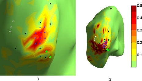
Figure 3.

Illustration of a case where leakage suppression has been unsuccessful. a) The CTF optimized for V1 as in Figure 2b, zoomed closer into V1. White and black dots indicate areas for which leakage was supposed to be suppressed; b) novel estimator, which in addition to a) also attempts to suppress leakage from two locations close to V1 (light green dots). Although the imposed constraints are fulfilled (see CTF values in the direct vicinity of white, black and green dots), the CTF is very widespread and patchy, and not focused around V1 as desired.
