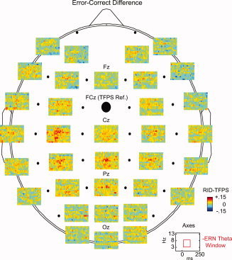
Figure 7.

The spatial localization of the baseline corrected error–correct difference phase synchrony based on the RID‐TFPS. The average phase synchrony surfaces across subjects depicting variation of the error–correct difference phase locking values for a subset of electrodes are shown.
