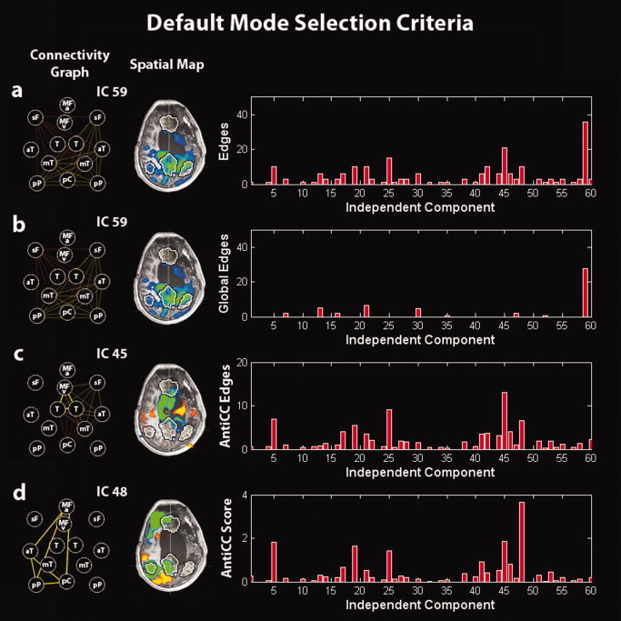
Figure 1.

Illustration of the default‐mode selection method in a minimally conscious‐state patient. (a) Selection of the IC corresponding to the graph with the highest number of edges. (b) Selection of the IC corresponding to the graph with the highest number of global edges (to select the global signal IC). (c) Selection of the IC corresponding to the graph with the highest number of anticorrelation‐corrected edges. (d) Selection of the IC corresponding to the graph with the highest anticorrelation‐corrected score. Right panel: (a) number of edges, (b) number of global edges, (c) number of anticorrelation‐corrected edges, and (d) anticorrelation‐corrected score of each graph vs. the corresponding IC number. Middle panel: Spatial map of the selected IC. Left panel: Connectivity graph of the selected IC. MFv, medial prefrontal cortex ventral; MFa, medial prefrontal cortex anterior; pC, posterior cingulate/precuneus; pP, posterior parietal lobe; sF, superior frontal gyrus; aT, middle temporal gyrus anterior; mT, parahippocampal/mesiotemporal; T, thalamus. Left is right side of brain.
