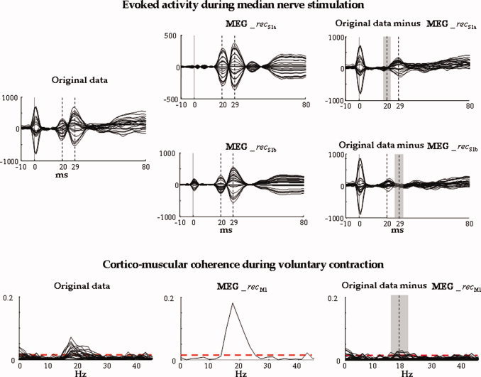
Figure 6.

Evoked activity during median nerve stimulation in one representative subject. All parietal channels' superimposition averaged on median nerve stimuli, in the time window [−10, 80] ms, t = 0 the stimulus arrival being at wrist (vertical solid line). The time points corresponding to M20 and M30 components are indicated (vertical dashed lines). Left: Original data. Centre: Retro‐projected data with only the S1a source (top, MEG_recS1a) and with only the S1b source (bottom, MEG_recS1b). Right: Original data minus MEG_recS1a (top) and original data minus MEG_recS1b (bottom). The grey area indicates the time interval (Δ2 t 20 + Δ1 t 20 + 1 up, Δ2 t 30 + Δ1 t 30 + 1, bottom) where the discrepancy indices (discrS1a up, discrS1b, bottom) are calculated. Note that both S1a and S1b well explain the generated field at their respective latencies. Cortico‐muscular coherence during voluntary contraction. Superimposition of all channels' coherences with the rectified EMG in the frequency window [0, 45] Hz. The confidence limit is indicated (0.015, horizontal dashed line). Left: Original MEG channels. Centre: Retro‐projected channels with only M1 (MEG_recM1). All channels display the same coherence with the EMG signal; this is because all the channels obtained by retro‐projecting only one FS display the same time evolution, unless a multiplicative factor and the coherence are independent from the signals amplitude. Right: Original MEG data minus MEG_recM1 channels. The grey area indicates the frequency interval (Δ2ωmax + Δ1ωmax + 1) where the discrepancy index (discrM1) is calculated. [Color figure can be viewed in the online issue, which is available at www.interscience.wiley.com.]
