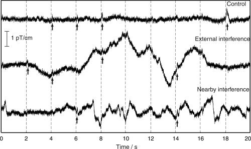
Figure 2.

Original signals from one left‐temporal‐lobe gradiometer channel during the Control condition (top), External interference condition (middle), and Nearby interference condition. Stimulus times are denoted by dashed vertical lines. Arrows point to visible auditory responses.
