Figure 3.

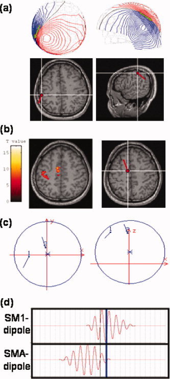
SM1‐ and SMA‐dipole allocation in simulation studies. (a) SM1‐dipole position and moment. The SM1‐dipole placement in the left SM1 was based on the equivalent current dipole (ECD) fit to movement evoked field I. Upper panel displays the isocontour maps of the recorded neuromagnetic signals and the dipole (in green). The SM1‐dipole was rendered onto the subject's own MRIs in axial view (lower panel; subject's right hemisphere to the right of the image). Anatomically, this SM1‐dipole was located slightly posterior to the contralateral central sulcus. (b) SMA‐dipole position and moment. The SMA‐dipole was seeded in the left SMA (right panel) close to the midline with coordinates adopted from a parallel fMRI experiment conducted by the same subject (left panel). (c) Spatial relationship between SM1‐ and SMA‐dipoles. Left, axial view; right, sagittal view. (d) Time courses of SM1‐dipole (upper panel) and SMA‐dipole (lower panel). In this simulation, the time course of the SMA‐dipole preceded that of SM1‐dipole by 600 m (Erdler et al., 2000; Lang et al., 1991). The blue line denotes the time‐point for the ECD fit in the subsequent analysis (see Fig. 7a).
