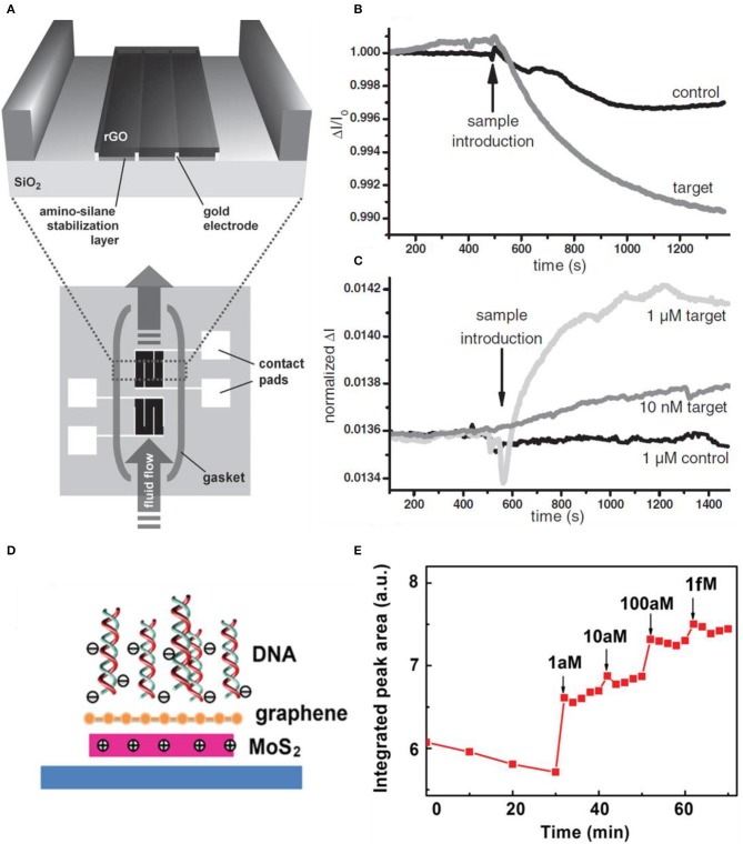
Figure 10.
RGO FET for real-time DNA detection. (A) Schematic diagram of RGO FET. RGO is deposited on top of the pre-fabricated electrodes. The two devices are isolated, to eliminate non-specific biological adhesion (bottom), which acts as a reference device. (B) RGO FET sensing curves toward DNA. Non-specific binding (control curve) occurs to the first device (bottom device in (A). (C) Second device curves having much more selectivity toward the target DNA. Figures (A–C) were reproduced from Stine et al. (2010) with permission from Wiley. Graphene/MoS2 heterostructures for detection of DNA. (D) Scheme of the charge distribution when DNA becomes adjacent. (E) Photoluminescence response of graphene/MoS2 to increased concentration of the target DNA. Figures (D,E) were reproduced from Loan et al. (2014) with permission from Wiley.

