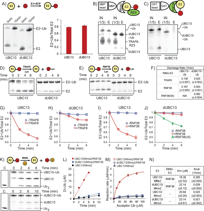
Figure 10. Activation of UBC13 ~ Ub conjugates by RING domains.
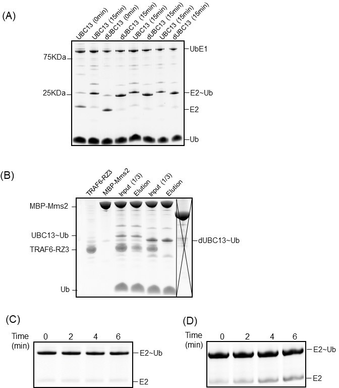
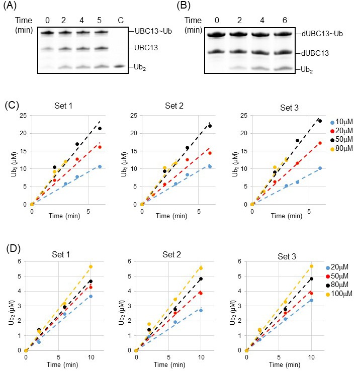
(A) A comparison of Ub conjugation to UBC13 and dUBC13. E1, ATP, and UBC13/dUBC13 were incubated in reaction buffer for 15 min, quenched by adding EDTA and separated on SDS page. The amount of E2 ~ Ub conjugates were quantified and plotted in the right section. The values are the mean of three reactions, and the error is the standard deviation of the same. (B) Affinity pull-down experiment was performed by incubating MBP beads with MBP-Mms2, UBC13 ~ Ub (or dUBC13 ~ Ub) and TRAF6RZ3, washed thoroughly and separated on SDS gels. The asterisk denotes impurities. (C) Affinity pull-down experiment was performed by incubating GST beads with GST-RNF38RING and UBC13 ~ Ub (or dUBC13 ~ Ub), washed thoroughly and separated on SDS gels. (D) Single-round discharge of Ub from UBC13 ~ Ub and dUBC13 ~ Ub catalyzed by TRAF6RING was monitored. UBC13 was conjugated with Ub, and the reaction was quenched. Then Mms2, TRAF6RING, and Lysine were added to the reaction mixture, and E2 ~ Ub and free E2 was monitored over time. The proteins bands in (D) were quantified and plotted in (G) and (H). The plotted values are the mean of triplicates, and the error is the standard deviation of the same. (E) Same as in D), where the discharge is catalyzed by RNF38RING domain. The proteins in (E) are quantified and plotted in (I) and (J). The rate of discharge in each case was calculated as discharge-rate = (Total E2-E2 ~ Ub)/(Total E2.time) for the initial time points and given in (F). (K) The rate of Ub2 synthesis was monitored over time. UBC13 or dUBC13 was conjugated with Ub, and the reaction was quenched. Then Mms2, RNF38RING and Acceptor Ub was added to the reaction mixture, and the synthesis of Ub2 was monitored over time. (L) The rate of Ub2 synthesis for UBC13 and dUBC13 are compared at substrate (acceptor-Ub) concentration of 50 μM. (M) The reaction rates for UBC13 and dUBC13 are compared at various substrate concentrations. (N) The kinetic parameters of Ub2 synthesis for UBC13 and dUBC13 are given in a table. The values are the mean of triplicates, and the error is the standard deviation of the same. The Ub used in all the experiments of this figure is K63A-Ub, except the acceptor Ub used in (K)-(M) is D77-Ub.
Figure 10—figure supplement 1. Kinetics of Ub conjugation, RING-binding, and Ub-discharge.

Figure 10—figure supplement 2. Kinetics of Ub2 synthesis.

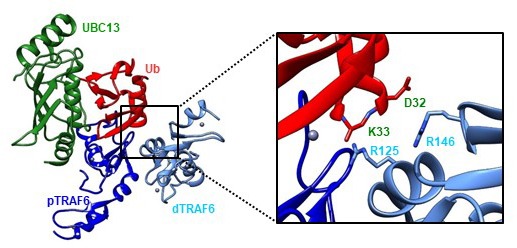
Figure 10—figure supplement 3. Stabilization of the UBC13 ~ Ub conjugate by the TRAF6 homodimer.


