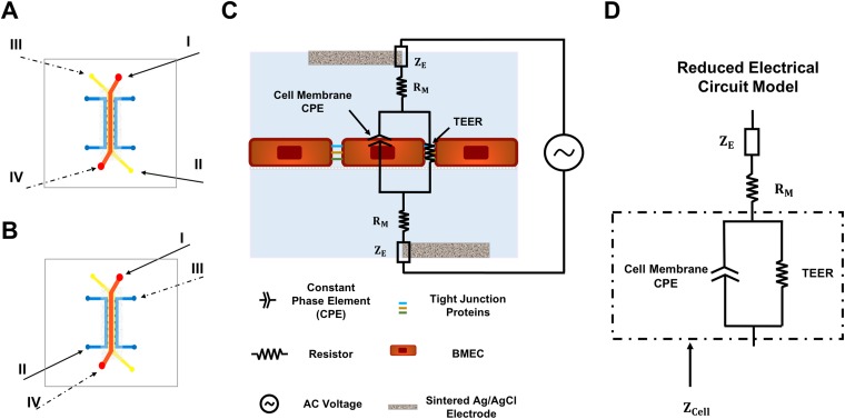
FIG. 5.
Electrode placement for 2-point impedance spectroscopy and the electrical circuit model of the device. (a) and (b) Schematics showing the inlets used for placement of electrodes for devices without a hydrogel (a) and with a hydrogel (b). For the two-probe measurement, measurements are made by inserting the electrodes into reservoirs I and II (solid arrows) or III and IV (dashed arrows). (c) The electrical circuit diagram for the device with BMECs showing the various elements that contribute to the overall impedance. (d) The reduced electrical circuit model that was used for fitting the measured data and finding the electrical properties of the cellular barrier.

