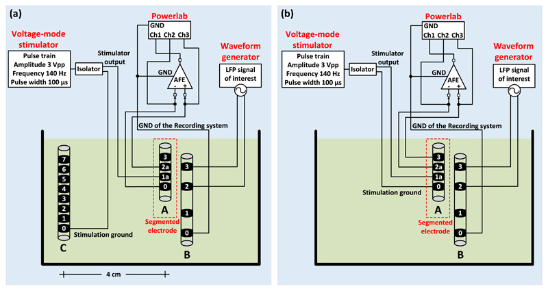
Figure 3.
The in vitro experimental setup for unipolar (a) and bipolar (b) stimulation. A DBS electrode (electrode A in (a) and (b), model DB-2201, Boston Scientific Neuromodulation) was placed in a glass container filled with tyrode solution at room temperature. The monophasic stimulation pulses (3 V peak-to-peak amplitude, 140 Hz frequency and 100 μs pulse width) were delivered by means of a commercial stimulator (Grass, Astromed, Inc., USA) and the LFP signals (representing the LPF signals recorded from the human neural tissue in a typical post-operative LFP recording session) were injected to the solution by an Agilent 33220A waveform generator. The LFP signals were injected to the solution as a differential signal through a second electrode (electrode B in (a) and (b), model 401261, St. Jude Medical). One of the four contacts of electrode B was connected to the ground of the recording system. In both unipolar and bipolar settings the stimulation ground was electrically isolated from the mains by using a commercial isolator (SIU5 stimulus isolation point, Grass, Astromed, Inc., USA). The LFP signals recorded by the proposed AFE were digitized at a sampling frequency of 20 kSPS (samples per second) and depicted on a computer by the Powerlab data acquisition system (ADInstruments). (a) In the unipolar stimulation setting, we sense differentially and symmetrically in space about the unipolar stimulation contact 1a of electrode A by sensing across the two nearest, equi-distant to contact 1a, neighbour contacts (contacts 0 and 2a). However, since the surface areas of contacts 0 and 2a differ, the sensing is not completely symmetrical and thus some differential-mode interference from stimulation is expected to appear and be suppressed by the analog notch filter of the proposed AFE. The anode (ground) of the stimulator was connected to one of the contacts of a third electrode (electrode C), which is the 8-contact Vercise DBS lead (Boston Scientific). Electrode C was placed approximately 4 cm away from the stimulation site and represents the case of the IPG, which acts as an anode in the unipolar stimulation setting. (b) In the bipolar stimulation setting, two contacts of electrode A (0 and 1a) were used for stimulation (anode and cathode of the stimulator) and another two for recording (2a and 3).

