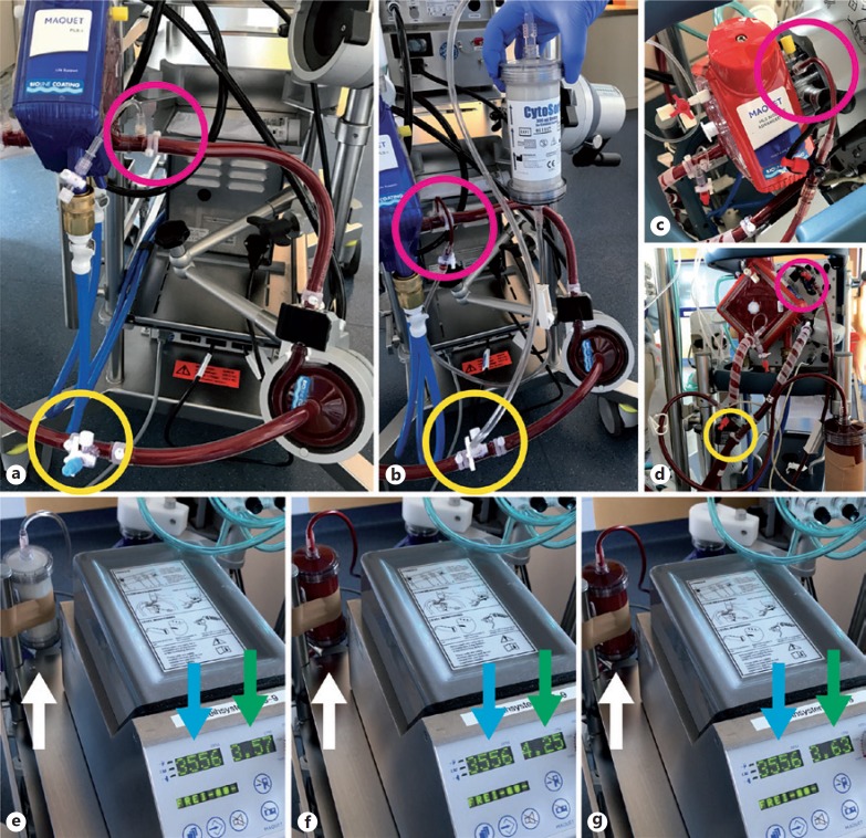
Fig. 2.
Connection of CytoSorb® into standard ECMO circuits. a Rotaflow® ECMO circuit with 3-way stopcocks for connection of additional devices before (yellow circle) and after (pink circle) the rotor. b Connecting the CytoSorb® inlet to the high pressure site (pink circle) and the outlet to the low pressure site (yellow circle) establishes a flow gradient through the adsorber. c and d Connection of Cytosorb® into a Cardiohelp® ECMO circuit. e ECMO flow before and after (f) starting blood flow through the CytoSorb®(white arrow), and after manually stopping blood flow again (g). Note the changes in total ECMO flow (green arrow) at unchanged rotor speed (blue arrow), demonstrating the shunt through the parallel CytoSorb® circuit.

