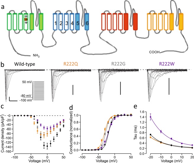
Figure 1.
Location of the R222 residue and activation properties of R222 mutant channels. (a) Topological representation of NaV1.4 channel. The four repeats (I-IV) of the channel are shown in green, blue, red and yellow, respectively. Each repeat contains six transmembrane helices (1–6) of which the first four (open) form a voltage-sensing domain (VSD). Helices 5–6 (filled) of each repeat form the central ion-conducting pore. Fourth transmembrane helix (S4) contains several arginine residues. R222 is the second outermost arginine (R2) in the S4 helix of the VSD-I (circled). (b–e) Characterization of the activation properties of R222 mutant channels. Wild-type data is shown in black symbols, R222Q in orange, R222G in grey and R222W in purple. See Table 1 for numeric data. (b) Representative main pore currents in response to voltage steps between −100 mV to +50 mV in 10 mV increments. Voltage protocol is shown in insert. Scale bars: x-axis 2 ms, y-axis 25 pA/pF. (c) Mean current density. (d) Voltage dependence of activation. Solid lines show Boltzmann equation fits to mean Conductance-voltage data. (e) Time constant of inactivation following channel opening. Solid lines represent a fit an exponential curve fit to mean time constant-voltage data.

