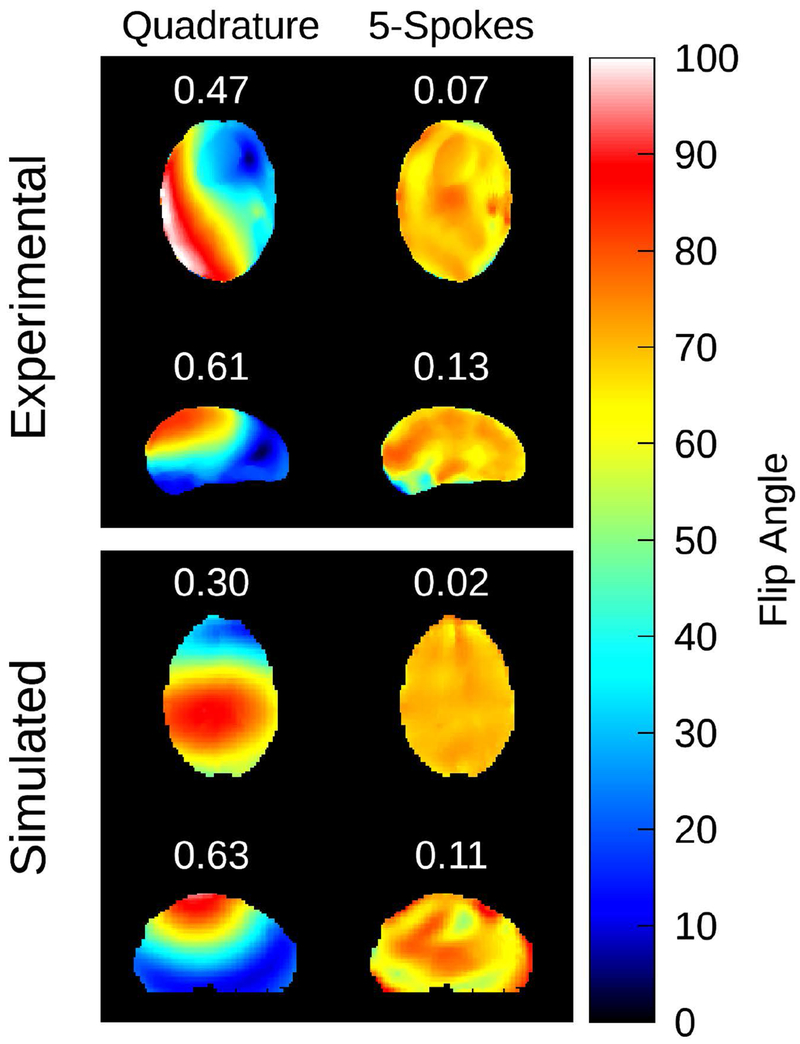
Figure 4:
Results of the parallel transmit spokes RF pulse calculation. In the left column, a flip angle map corresponding to the uHDC helmet in V2 configuration and the 2 channel transmit coil set to quadrature polarization is displayed. The predicted flip angle map after application of the spokes RF pulse is displayed in the right column. The target flip angle was set to 70 degrees. The coefficient of variation is printed above each map in white text. This RF pulse calculation was applied to both experimental (top) and simulated (bottom) cases. The application of a spokes RF pulse successfully mitigated the transmit inhomogeneity induced by the uHDC helmet in both scenarios.

