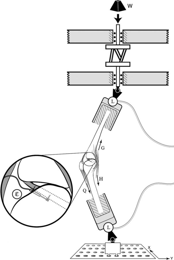
Fig. 1.
Schematic of the test setup, showing the knee mounted for testing as well as the applied impulsive loading (W) and two three-axis load cells (L). Lines of action of the quadriceps (Q), hamstrings (H), and gastrocnemius (G) muscle-tendon units are also visible. The inset shows the differential variable reluctance transducer attached to the anteromedial region of the anterior cruciate ligament in order to measure the relative strain (ɛ).

