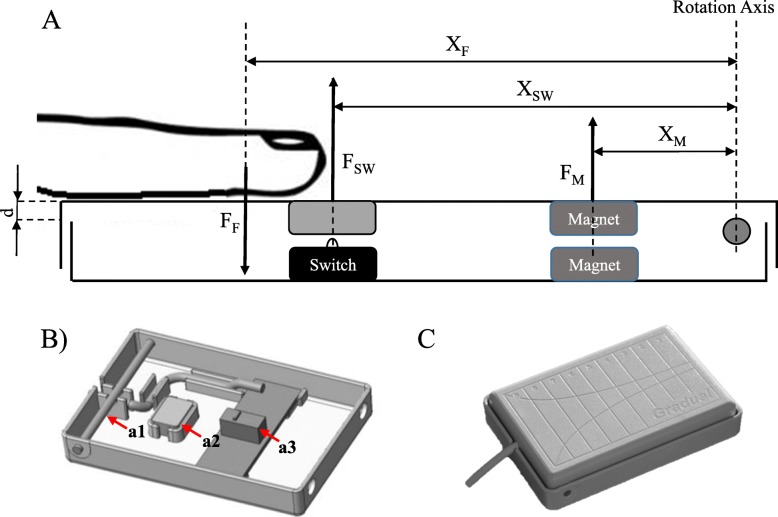
Fig. 1.
Diagram of LeMMS. a Schematic diagram of the LeMMS. FF is the finger exerted force, FM the repulsive force between magnets, FSW the force exerted by the micro-switch spring and XF, XM, XSW are the respective distances from the rotation axis. The vertical linear displacement d is the first approximation of the rotation angle. b LeMMS half-shell with brass pin (a1), magnet (a2) and micro-switch (a3). c Illustration of the LeMMS assembled

