Fig. 6.
Printed curved corneal scaffold utilizing bioinks with different concentrations
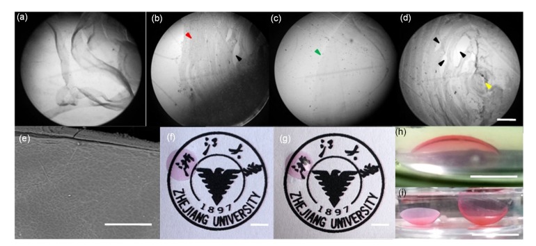
Micrographs of films with different bioinks (S-1, S-2, S-3, S-4), made with the same printing process at room temperature (scale bar=500 μm): (a) printed S-1 film was in a semi-solid state and easily unraveled at room temperature and the structure could not be formed; (b) due to the fluidity of the bioink, the film structure printed with S-2 was deposited from the centre to the edge (red arrow), and there were some gaps (black arrow) in the structure because of the bad combination of the bioink filament; (c) the edge and surface (green arrow) of the film printed with S-3 was smooth and integrated, and there was no obvious pattern in the structure; (d) the formability of printed S-4 film was poor, and the bioink filaments intertwined and became entangled with each other in the final stage of the printing process, resulting in uneven distribution of bioink (yellow arrow). (e) Scanning electron microscope (SEM) image of the top surface of a printed film (scale bar=200 μm). (f) Printed flat film with good transparency (scale bar=5 mm). (g) Printed curved film with good transparency (scale bar=5 mm). (h, i) Examples of 3D printed calcium alginate-gelatin film with S-3 in an equilibrated hydrated state (scale bar=5 mm (h) and 10 mm (i), respectively) (Note: for interpretation of the references to color in this figure legend, the reader is referred to the web version of this article)

