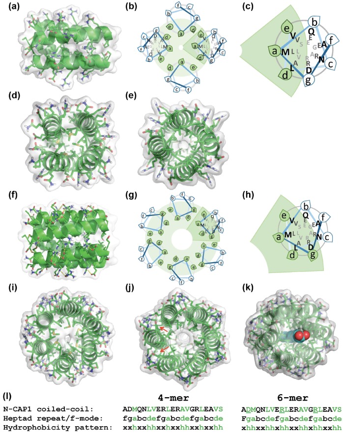
Figure 3.
Modeling oligomerization of the N-terminal constructs of human CAPs: the CCBUILDER 2.0 web application (http://coiledcoils.chm.bris.ac.uk/ccbuilder2) was used to model the oligomeric coiled-coil structures of CAP1 (shown) and CAP2 N-terminal helices. The most stable tetramers (a–e) and hexamers (f–j) with the lowest energies are shown from three perspectives: side view (a,f), and along the helices from the N- (d,i), and C-termini (e,j). Schematic helical wheel diagrams show the relative orientations of the helices in the oligomers (b,g) and an enlarged view of the highlighted helices (c,h). Green shaded areas represent the hydrophobic cores of the oligomers. Up to four salt bridges between Arg and Asp/Glu residues contribute to the stabilization of each pair of neighboring helices (shown as yellow dotted lines in (f)). (k) Hypothetical stabilization of the hexamer structure by a fatty acid (blue) occupying the central, hydrophobic channel of Srv2/CAP (see Section 3). A low-energy CAP2 structure generated in CCBUILDER is shown. (l) The N-terminal coiled coil sequence of CAP1 (top row), with the conventional “a–f” designation of the heptad amino acids (middle row) and the hydrophobicity pattern (bottom row) characteristic of trimeric/tetrameric (xxhxxhh) and higher-order (xhhxxhh) coiled-coil structures. Residues involved in stabilization of the hydrophobic cores are designated by “h” in the hydrophobicity pattern and by green color elsewhere. Notice that in the hexamer, Cβ-Cγ atoms of the underlined Arg residues (l) contribute to the stabilization of the hydrophobic core (red arrows in (j).

