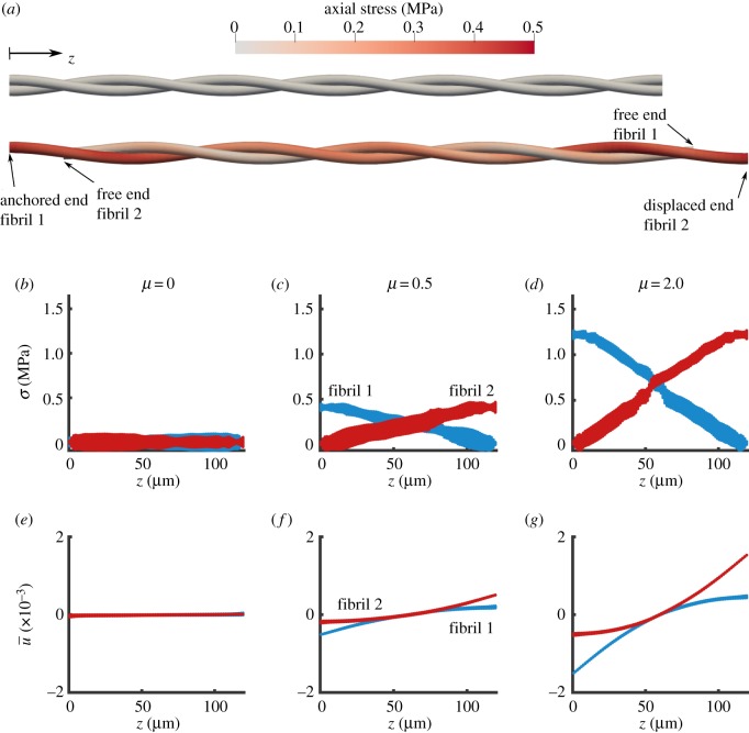
Figure 6.
FE simulation of two helically wrapped fibrils. (a) Axial stress distribution in the fibrils for the undeformed (top) and deformed (bottom) states for µ = 0.5. The geometrical scale is compacted 10 times in the axial direction for clarity. (b–d) Stress along the length of the fibrils, and (e–g) normalized displacement (, equation (2.4)) along the length of the fibrils for various choices of friction coefficient µ. With no friction (µ = 0), there was no σ or (b,e). As the frictional coefficient increases, the stress and the deformation increases for µ = 0.5 (c,f) and for µ = 2 (d,g). The model parameters are E = 1 GPa, ν = 0.2, λ = 40 µm. (Online version in colour.)

