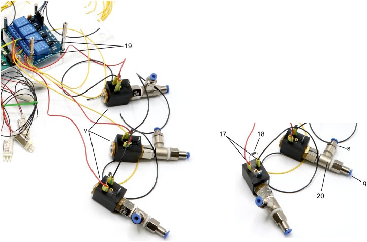
Appendix 1—figure 15. Illustration of step 17-20.
17. Solder red and black wires (approx. 10 cm) to contacts of 3 × 2/2 solenoid valves (v).
18. Include a diode (1N4007) between the contacts to avoid current from capacitor discharge damaging the remaining circuit.
19. Connect 2/2 solenoid valves to the 4-channel relay. Connect the red cable to the normally open contact and a yellow cable (approx. 10 cm) to the common contact. Document which relay is connected to each solenoid valve.
20. Screw on push-in fittings (s, q) onto the 2/2 solenoid valves.

