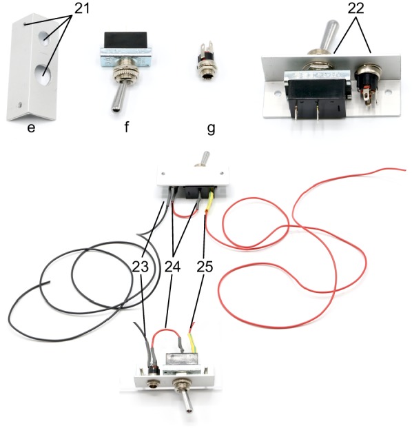
Appendix 1—figure 16. Illustration of step 21-25.

21. Drill holes (3, 8, 12 mm) in aluminium angle (e) as shown on the layout.
22. Attach the toggle switch (f) to the 12 mm hole and the DC barrel power connector (g) to the 8 mm hole.
23. Solder a black wire (approx. 10 cm) to the neutral conductor of the power connector. This wire will connect to all ground wires (black wires) of the valves and relays.
24. Solder a red wire to the DC conductor of the power connector and to a contact of the ON/OFF switch.
25. Solder another red wire (approx. 10 cm) to the other contact of the toggle switch. This wire will condcut 12V for all valves and relays (yellow wires).
