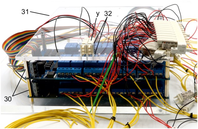
Appendix 1—figure 18. Illustration of step 30-32.

30. Screw in second 25 mm metal spacer (i) on top of all metal spacers to create level pillars of metal spacers for the upper acrylic plate.
31. Mount upper acrylic plate (5 mm) on top of the 25 mm metal spacers (i).
32.Use 20 mm M2 bolts to attach the non-manifold 3/2 solenoid valves (y) at the location of the 2 mm holes on the upper acrylic plate. Use M2 nuts below the acrylic plate to fix the valves.
