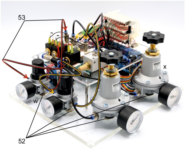
Appendix 1—figure 23. Illustration of step 52-43.

The following steps connect the 1–10 bar pressure regulators (w) to the pressurized air supply and the 2/2 solenoid valves.
52. Position the pressure regulators (w, x) on the base plate and fix them using double sided adhesive tape. We found this to be of sufficient stability. Pay special attention to the intended direction of air flow depicted on the regulators.
53. Connect the PE-tubes to the multiple distributor with four outlets and to the 1–10 bar pressure regulators (w). Then connect those to the 2/2 solenoid valves as depicted. Meaning of color code and arrowheads correspond to the previous steps.
