. 2019 Nov 19;8:e48178. doi: 10.7554/eLife.48178

Figure 2. Automated pressure system.

(A) Tubing scheme between the different pneumatic components. Top row depicts pressure regulators and their set pressure for each path. 2/2 valves are solenoid valves with two ports and two positions (open or closed). 3/2 valves are miniature solenoid valves with three ports and can switch between two positions connecting either inlet to one outlet. An illustrated step-by-step assembly guide of the pressure system can be found in Appendix 1. (B) Screenshot of Matlab GUI controlling the pressure system. It communicates with an Arduino microcontroller board which in turn has digital outputs connecting onto a relay board. For further details of wiring scheme see Figure 2—figure supplement 1. For more information on GUI see appendix 2. (C) Photograph of an assembled pressure system.

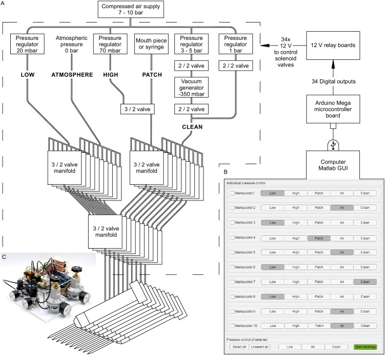
Figure 2.

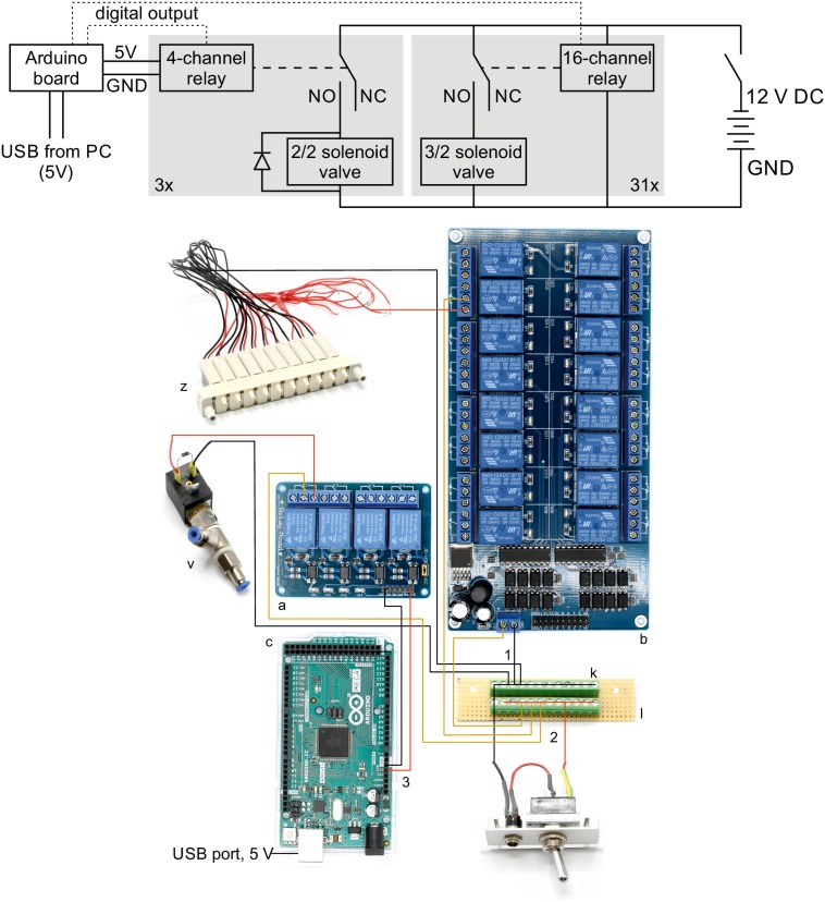
Figure 2—figure supplement 1. Wiring scheme of pressure system.

Figure 2—figure supplement 1.

Top: Electrical circuit wiring diagram for valves, relays and Arduino board. This wiring diagram shows that all solenoid valves (z, v) and the two 16-channel relay board (b) are powered through the 12 V DC power supply (80 W, 12 V / 6,67 A). The four-channel relay is powered through the Arduino board which receives a 5 V power supply from the USB cable. The gray boxes indicate that this circuit is replicated for each valve in parallel. The relays receive digital signals from the Arduino boards (dotted lines) and switch the contacts from NC (normally closed) to NO (normally open) which brings the solenoid valve into a different state. A flyback diode is necessary for the 2/2 solenoid valves to protect from voltage spikes. Bottom: Photographic wiring scheme of circuit. (1) Ground conductor is connected to all black lines through the soldered screw block on the stripboard (k, l). (2) The 12 V phase conductor (red) is connected to all yellow lines through the other soldered screw terminal block. These yellow wires carry 12 V to power the 16-channel relay board (b), the individual 3/2 solenoid valves (z) and the 2/2 solenoid valves (v). (3) The 4-channel relay board (a) is powered through the 5 V output pin of the Arduino board (c) which is supplied through the USB-cable from the PC.