Table 1.
Electrical stimulation parameters used in this study.
| Group Name | Stimulation Parameters | Charge Balance | Duty Cycle | Cathodic Charge | Anodic Charge | Waveform Shape |
|---|---|---|---|---|---|---|
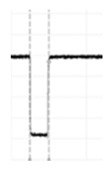
| Monophasic Cathodic | F = 50 Hz PW = 50 μs |
Unbalanced | 0.25% | 7.5 nC | 0 |
|
| Asymmetric Biphasic 1:0.5 (AsymBi 1:0.5) |
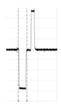
F = 50 Hz PW = 50 μs cathodic, 25 μs anodic |
Active unbalanced | 0.38% | 7.5 nC | 3.8 nC |
|
| Symmetric Biphasic 1:1 (SymBi 1:1) |
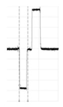
F = 50 Hz PW = 50 μs per phase |
Active balanced | 0.50% | 7.5 nC | 7.5 nC |
|
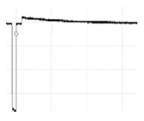
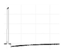
| Cathodic PR | F = 50 Hz PW = 60μs ‡ |
Passive balanced | 5% * | 9.0 nC | 9.0 nC |
|
| Anodic PR | F = 50 Hz PW = 60 μs ‡ |
Passive balanced | 5% * | 9.0 nC | 9.0 nC |
|
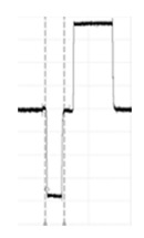
| Asymmetric Biphasic 1:2 (AsymBi 1:2) |
F = 50 Hz PW = 50 μs cathodic, 100 μs anodic |
Active unbalanced | 0.75% | 7.5 nC | 15 nC |
|
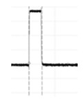
| Monophasic Anodic | F = 50 Hz PW = 50 μs |
Unbalanced | 0.25% | 0 | 7.5 nC |
|
F = Frequency, PW = pulse width. Charges are mean values. Duty Cycle = (PWcathodic + PWanodic) × F. *, PW for balancing phase approximated to be around 1 ms. ‡, PW of leading phase.
