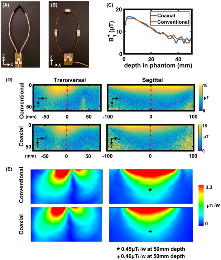
Figure 6.

Photographs of a (A) SCC elongated loop and (B) conventional elongated loop. (C) Measured profile along the central axis of the antenna (red dashed line in D). (D) Measured transversal and sagittal maps of conventional and SCC coils. (E) Simulated transversal and sagittal maps of conventional and SCC coils
