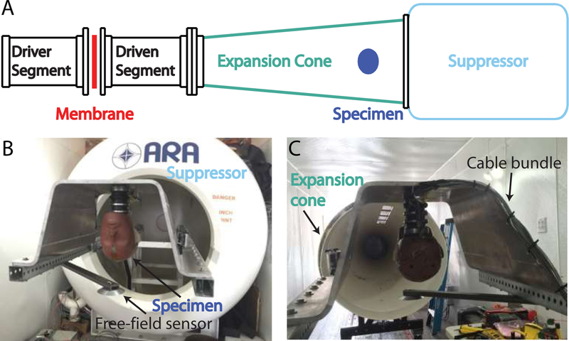
Fig. 3:
Shock waves were generated with a 45 cm diameter shock tube mounted inside a semi-trailer (A). The specimen (a Hybrid III dummy head shown here) was mounted (B) inside the expansion cone (C) of the shock tube, held in place up-side down inside an aluminum mount, affixed to a steel frame. A pancake-style free-field pressure gauge was mounted adjacent to the specimen’s head (slightly forward of the forehead). The bundle of wires and fiber-optic cabling were run up the neck, along the back of the aluminum mount, and attached to the steel supports, to protect the bundle from the shock wave.

