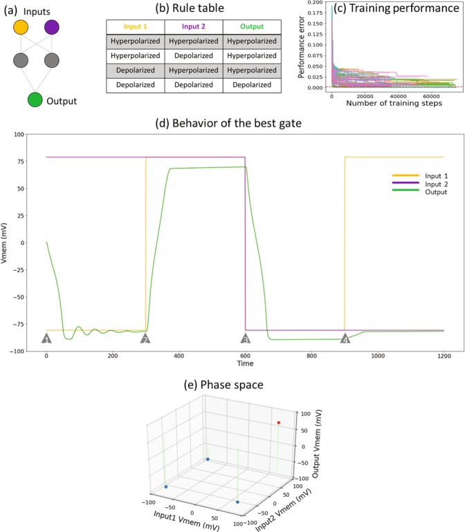
Figure 2.
The AND gate. (a) A schematic of the AND logic gate and its rule table. The orange and purple cells are the inputs, and the green cell is the output; the grey cells are intermediate cells offering computational support. (b) Specification of the output Vmem for various combinations of input Vmem levels. This is known as the “truth table” in the Boolean logic literature, where the “hyperpolarized” state (around −80 mV) is indicated as “0”, “False” or “OFF” and the “depolarized” state (around +80 mV) as “1”, “True” or “ON”. This rule table essentially summarizes the mechanism of the BEN-based AND gate: the output is depolarized only when both of its inputs are depolarized; in Boolean logic terms the output is ON only when both inputs are ON. (c) Pareto front of training errors over time (one unit is equal to a single training epoch) for the AND gate. This plot depicts the “front” with the best errors achieved over time. This figure demonstrates that the training does indeed result in learning. (d) The behavior of the best AND gate shown in the form of time series of the input and output nodes of the gate, shown for all four input-output conditions generated in a random sequence. The red and blue lines represent the states of the two input nodes, and green represents the output. The grey triangles mark the time points at which the inputs are switched to a different state. For example, both inputs are hyperpolarized at time point (1), while at time point (2) the red input is depolarized. (e) The dynamical phase of the logic gate:a depiction of a set of trajectories in the input-output space, illustrated in a time-lapse style. This dynamical system has two attractors in the output space, highlighted in filled red (depolarized state) and blue (hyperpolarized state) circles. The trajectories look straight because the inputs are fixed, and only the output changes.

