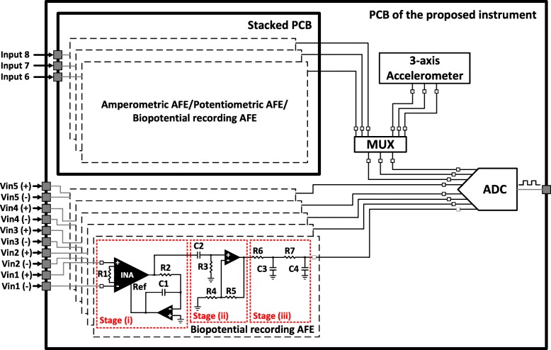
Fig. 2.
Block diagram showing the overall AFE and the ADC section of the proposed instrument. The overall AFE consists of eight channels (five channels on the main printed circuit board (PCB) of the instrument and another three channels on a stacked PCB that is adjusted on two headers located on the main PCB). The biopotential recording AFE consists of three stages: (i) a differential pre-amplification stage with high-pass characteristics, (ii) an active, 1st order high-pass filter that enhances the dc offset rejection capabilities of the AFE and (iii) a passive, 2nd order low-pass filter that defines the passband of the AFE and also serves as an anti-alias filter for the ADC stage, which follows in the signal chain. The inputs of the first five channels are differential, whereas the inputs of channels 6, 7 and 8 can either be differential or single-ended depending on the type of biosignals (either amperometric or potentiometric or biopotential signals or a combination of them) the stacked PCB is intended to record

