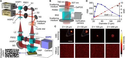
Fig. 2. Experimental setup and characterization of GePGS optical focusing.

(A) Schematic illustration of the experimental setup. HWP, half wave plate; PBS, polarizing beam splitter; S, shutter; M, mirror; L, lens; BS, beam splitter; TIRP, total internal reflection prism; DMD, digital micromirror device. (B) Setup for quantifying the GePGS-guided focusing inside a scattering medium. (C) Normalized (Norm.) intensity distributions of the optical foci in between two scattering media with different diameters (D) of guide stars. Top row, with 637-nm light switching; bottom row, without 637-nm light switching. Each image is self-normalized. Scale bar, 300 μm. (D) PBRs of the foci with different GePGS diameters, and the corresponding SNRs of the captured holograms.
